Pavel is very careful with RFI/EMI management. Puts Ott into practice.
Also unusual compared to some, he has friends that are very skilled listeners and he places trust in their listening impressions.
Also unusual compared to some, he has friends that are very skilled listeners and he places trust in their listening impressions.
Last edited:
imagine that there are 2 photos in front of you. One clear, photographed with a properly set aperture. And the second is blurry, without focus. How do you explain why they differ. So it is with sound.Those sound like timing issues and yet the system is already bandwidth limited, what is your explanation for the perceived differences?
Maybe the analogy was referring to perceptual experience, not underlying causation?
Analogies always fail when picked apart.
Analogies always fail when picked apart.
Timing issues, or reduced non-stationary low-level noise and distortion because of less disturbance of amplifier linearity/stationarity
This salad needs some dressing.
I will repeat once again, since the first time it is not clear. Your example is not representative due to the different frequency of the unity loop gain of the two samples. It goes without saying that one of them will get out of the overload faster.How do the examples I give do not meet your requirements? If mine doesn't suit you - bring yours and prove otherwise
or do you not understand what you are talking about? writing to show off?
And I remind you that the burden of proof lies with the approver. Since you assert about the presence of some "speed distortion", then prove to you, not to me. And it is very likely that you do not understand what you are talking about and writing in order to show off.
And what do we see in these figures and how do they prove the existence of distortions in the first period, or the so-called "velocity distortions"? I see a response to a step signal that has nothing to do with the normal operation of the amplifier, since the comparison node exits linear mode. What kind of sound quality can we talk about at all?unlike the talkers, I do specific things. Here is the result of checking one of the amplifiers
Skimmed through the thread, I found only a few posts confirming Graham's conclusions, the rest of the posts are idle chatter without any arguments. No one has ever refuted his conclusions.
I decided to look for the development of Graham's amplifiers and found the GEM amplifier circuit.
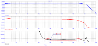
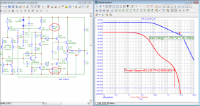
Here are the results of her testing. The Time Propagation Delay is only 33 ns, which is 3 times less than the minimum required for perfect amplification.
The spectrum is practically constant from the first period, and it is short, in the spectrum there is mainly the 2nd harmonic not exceeding 0.005%.
Group delay is almost constant in a wide range of high frequencies - up to 4 MHz
I have to ignore stupid comments and questions
I decided to look for the development of Graham's amplifiers and found the GEM amplifier circuit.
Here are the results of her testing. The Time Propagation Delay is only 33 ns, which is 3 times less than the minimum required for perfect amplification.
The spectrum is practically constant from the first period, and it is short, in the spectrum there is mainly the 2nd harmonic not exceeding 0.005%.
Group delay is almost constant in a wide range of high frequencies - up to 4 MHz
I have to ignore stupid comments and questions
Attachments
Last edited:
That is, in other words, you did not understand the arguments, so you chose to assume that they do not exist. Although, in fact, it is you who should justify your innovations. Ignoring quite legitimate questions, you demonstrate the inconsistency of your theory and the lack of argumentation of sufficient quality.Skimmed through the thread, I found only a few posts confirming Graham's conclusions, the rest of the posts are idle chatter without any arguments. No one has ever refuted his conclusions.
...
I have to ignore stupid comments and questions
This salad needs some dressing.
Caesar for me thanks. OTOH a Japanese sesame seed dressing is hard to beat on tofu with sliced green onion.
I prefer to make my own.
Virgin Olive Oil
White wine vinegar
Pressed garlic
Balsamic vinegar
Salt
Pepper
Sugar
(water)
Perfect for salads and vegetables.
Virgin Olive Oil
White wine vinegar
Pressed garlic
Balsamic vinegar
Salt
Pepper
Sugar
(water)
Perfect for salads and vegetables.
.......From the DIM-30 tests, it can be seen that the level of distortion.........
petr, I think you really should stop posting simulations and take what they spit out seriously, unless you convince me you have been using improved transistor models.
Thank you for posting your micro-cap schematic. I was able to simulate on it and was able to find out why the same amp #2 you posted HERE became an oscillator in my LtSpice simulation, yet shows a decent 10dB gain margin in your own simulation.
Turns out you are working on the rudimentary manufacturer's transistor models, that are not known for being anywhere near what the real world devices are.
Replaced the transistors with models improved by Bob Cordell for the small and medium power transistors, and models improved by fellow member keantoken (if I recall correctly) for the output transistors, the 10dB gain margin is not there anymore, and the amp turns into an oscillator too. Please see attached.


It's common knowledge that a simulation at best is only as good as the models are. It's hard to believe all the "enlightenment" you've been relentlessly preaching are based on simulation works of such poor quality and negligence. So please convince me not to believe.
It is a pity that Graham passed away (2014) without waiting for the recognition of his idea of the correct approach to the design of audio amplifiers. Personally, I came to a similar idea more than 10 years later based on vector and velocity distortions, which, like FCD, are related to time Propagation Delay.
Upside-Down Differential Amplifier
Unlike the "theorists", Graham practically proved the validity of his idea
nattawa, you didn't understand the main thing - Graham's idea! lay out the model with the correct transistors
Upside-Down Differential Amplifier
Unlike the "theorists", Graham practically proved the validity of his idea
nattawa, you didn't understand the main thing - Graham's idea! lay out the model with the correct transistors
Attachments
Last edited:
It is a pity that Graham passed away (2014) without waiting for the recognition of his idea of the correct approach to the design of audio amplifiers. Personally, I came to a similar idea more than 10 years later based on vector and velocity distortions, which, like FCD, are related to time Propagation Delay.
Upside-Down Differential Amplifier
Unlike the "theorists", Graham practically proved the validity of his idea
nattawa, you didn't understand the main thing - Graham's idea! lay out the model with the correct transistors
Graham's idea was not recognized, not by a long shot, it was strongly contested. As is your 'idea'. The whole concept has been pushed by you but not in any way 'recognized', as can be seen by reading this thread.
Your inverting this thread to say it is recognized is pure BS and your constant pushing does not make it true, not at all.
What is particularly sad is that knowledgeable members here have explained the phenomenon in clear engineering terms, which you have just ignored, either because you don't want to give up your precious but misleading opinion, or because you didn't understand it. Sad, either way.
Jan
Last edited:
Jan, I watched your duel with Graham. Graham tried his best to explain to you the difference between distortion in the steady state and distortion at the beginning of the signal - but you still did not understand anything.
At the beginning of the signal, there are distortions associated with transient processes that depend on the behavior of the group delay. These processes are often called linear only because they do not depend on the signal level, but this does not make the signal any easier. In fact, linear distortion occurs only after the end of the transients.
Graham did not even find such a term as "linear distortion" in the reference book, he found only "linearity", but this is not the same thing!
What is usually measured using Audio Precision refers to nonlinear distortion and can have a negligible level, while the speed distortion, which devices do not measure, can be tens and hundreds of times higher - they are responsible for the sound quality.
Then they are surprised - THD = 0.01%, and the sound is disgusting
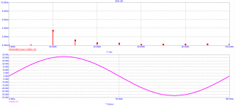
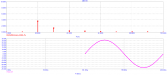
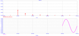
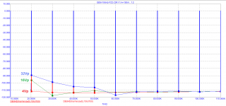
Let us turn to the spectrum of harmonics of a signal with a frequency of 10 kHz in the first period of the GEM amplifier. The spectrum at an output voltage of 4 V (peak) is indicative. The distortion level does not exceed -110 dB (<0.0003%). This is the level of all distortion (non-linear and transient).
With an increase in the output voltage level, there is no increase in higher harmonics (as in the best tube amplifiers - above 5 kHz).
At one time, everyone thought and were sure that the earth was flat and this was widely supported, but this does not mean that it was in fact.
Graham actually proved the correctness of his idea. Eternal memory and honor to him!
At the beginning of the signal, there are distortions associated with transient processes that depend on the behavior of the group delay. These processes are often called linear only because they do not depend on the signal level, but this does not make the signal any easier. In fact, linear distortion occurs only after the end of the transients.
Graham did not even find such a term as "linear distortion" in the reference book, he found only "linearity", but this is not the same thing!
What is usually measured using Audio Precision refers to nonlinear distortion and can have a negligible level, while the speed distortion, which devices do not measure, can be tens and hundreds of times higher - they are responsible for the sound quality.
Then they are surprised - THD = 0.01%, and the sound is disgusting
Let us turn to the spectrum of harmonics of a signal with a frequency of 10 kHz in the first period of the GEM amplifier. The spectrum at an output voltage of 4 V (peak) is indicative. The distortion level does not exceed -110 dB (<0.0003%). This is the level of all distortion (non-linear and transient).
With an increase in the output voltage level, there is no increase in higher harmonics (as in the best tube amplifiers - above 5 kHz).
At one time, everyone thought and were sure that the earth was flat and this was widely supported, but this does not mean that it was in fact.
Graham actually proved the correctness of his idea. Eternal memory and honor to him!
Last edited:
imagine that there are 2 photos in front of you. One clear, photographed with a properly set aperture. And the second is blurry, without focus. How do you explain why they differ. So it is with sound.
What do you think causes it? BTW, high frequency distortions can lead to the perception of "clarity"
Petr, neither you nor Graham understood/understand that this is not distortion but naturally follows from bandwidth limiting and generally from the shape of the transfer function.
Nobody in his right mind would call this distortion. That is the tragic you share with Graham.
So there is no common base for discussion.
Jan
Nobody in his right mind would call this distortion. That is the tragic you share with Graham.
So there is no common base for discussion.
Jan
@petr_2009
We have another distinguished member, Bohumil Federmann from Czech republic, he too paid great obsession to audio amplifier delay influence on listening quality, you might be interested in his work.
Influence of the delay amplifiers for listening characteristics
More information can be found on his web page.
Bohumil Federmann
Enjoy.
I prefer to make my own.
Virgin Olive Oil
White wine vinegar
Pressed garlic
Balsamic vinegar
Salt
Pepper
Sugar
(water)
Perfect for salads and vegetables.
Ah - that does sound good!
🙂
- Home
- Amplifiers
- Solid State
- First cycle distortion - Graham, what is that?