please, give a link to literature sources in which this problem is solvedAs far as I know, the feedback amp behavior described as the so called "speed distortion" or "speed error" has long been sorted out
The feedback errors, perceived as "transient" or not, by itself is not a problem. A non-problem does not need a solution. What I meant by "sorted out" in previous post is "to have understood".
Graham recommended driving the signal to the amplifier's output through a load. This method is often used to measure the output impedance. His opponents did not seem to know how to do this, otherwise they would have learned more about the work of the NFB and would not laugh at him.
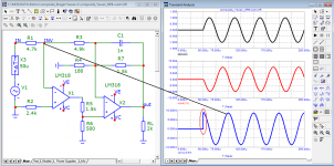
Here are a couple of tests that show that speed distortions are inherent in the very mechanism of NFB. In the steady state, they do not occur, speed distortions occur at the beginning of the period and at any voltage deviation from the sinusoidal one. Feedback works after the fact, with delay, with delay. And in order for the NFB operation to be invisible, the signal propagation delay time must be less than 100 ns.
This parameter has now begun to be indicated in expensive prestigious reference amplifiers. The animation shows the result of the addition of sine and cosine voltages.
Attachments
Feedback works after the fact, with delay, with delay.
Not again! How can it be that after all these years people still do not grasp the difference between phase shift and delay??
If you think this, no wonder the rest of your thoughts fall apart! Please, please, read up on feedback and control from a good source.
Jan
Not again! How can it be that after all these years people still do not grasp the difference between phase shift and delay??
If you think this, no wonder the rest of your thoughts fall apart! Please, please, read up on feedback and control from a good source.
Jan

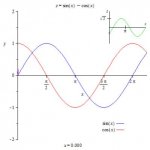
If the horizontal axle is time then how can the red curve not be delayed compared to the blue curve. I can´t see it as anything else then being lagging behind the blue curve some part of the wave form, or should I just merge the two waves in my head and keep repeating the mantra "phase is not delay" over and over???
Last edited:
Feedback works after the fact, with delay, with delay.
Not again! How can it be that after all these years people still do not grasp the difference between phase shift and delay??
If you think this, no wonder the rest of your thoughts fall apart! Please, please, read up on feedback and control from a good source.
Jan
If you consider a passive low pass network, the initial phase shift at the transient is that of the steady state. By this the first cycle must delay to catch the phase shift. In feedback amplifiers as were the tube ones, had their OLBW that of the OPT in most cases over 10khz, there was no problem with the first cycle. The transient response of a compensated feedback amplifier whose OLBW is only few hundred hertz, at transient, the amplifier starts with -90° phase shift, the feedback will bring it to steady state phase shift gradually, which can be only few degrees. The resultant transient has different delay than the WB version. If you want to hear what kind of distortion it results, Listen to "Happy together" by the Turtles, MP3 or not you will hear on most standard amplifiers a distorted choral (16) refrain. Requiems of Verdi and Mozart are the most difficult ones.
This problem can be systematically resolved if the OLBW is higher than 20khz.
ALL reactive circuits (L,C, all amplifiers) introduce phase shifts. It’s a physical and inescapable property of nature. OTOH, the speed of light, or an electric field in a conductor, takes a finite time to move from point A to point B (causality - a photon or an electric field cannot be in two places at the same time)
The two are not the same.
The first cycle delay you see is mostly due to phase shift and a small fraction of that the transit time around the circuit for the electrons. To minimize the phase shift, you have to increase BW. But you don’t know it’s phase shifted unless you peek with a scope - and it’s completely irrelevant since everything is shifted by the same amount (an amp is a minimum phase system). So it’s not actually first cycle delay, since all or the subsequent signal is also shifted.
This issue only becomes a concern when the amplifier phase shift is so high that it causes response peaking or oscillation- in which case it’s a question of getting the design right.
Last edited:
In a reactive component, either current leads (capacitor) or voltage leads (inductor).
In an amp, the Miller capacitor fed from a finite current (usually the LTP tail current) causes the voltage to lag while the current leads and that’s what causes this delay - nothing else. The VAS is an integrator and the delay we have been speaking about is well known, understood and discussed in engineering literature.
In an amp, the Miller capacitor fed from a finite current (usually the LTP tail current) causes the voltage to lag while the current leads and that’s what causes this delay - nothing else. The VAS is an integrator and the delay we have been speaking about is well known, understood and discussed in engineering literature.
View attachment 900092
If the horizontal axle is time then how can the red curve not be delayed compared to the blue curve. I can´t see it as anything else then being lagging behind the blue curve some part of the wave form, or should I just merge the two waves in my head and keep repeating the mantra "phase is not delay" over and over???
It just looks that way because a phase shifted sine is still a sine.
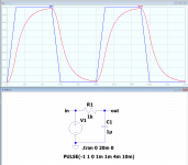
Thy it with a square wave or a triangle. You will see a phase shift, but not delay because if you look at the switching point of the input you will see that the switching point of the output wave is at exactly the same time! No delay (except some ns delay due to transit time, unrelated to feedback or circuit poles).
Another test: Send a current into a cap. We know that the voltage across the cap is phase shifted from the input current. If you use a sine it looks like the voltage is delayed because the integral of a sine is a shifted sine.
But using a square wave or triangle, again, you see that the cap voltage switches direction at exactly the same time when the input signal switches direction - no delay!
Jan
What if there was a positive phase shift, would you call it negative delay?View attachment 900092
If the horizontal axle is time then how can the red curve not be delayed compared to the blue curve. I can´t see it as anything else then being lagging behind the blue curve some part of the wave form, or should I just merge the two waves in my head and keep repeating the mantra "phase is not delay" over and over???
See attached. Lots of phase shift for the various spectral lines that make up the signal, but at the same point where the input wave switches direction, the output wave also switches direction. So there is no signal delay, only phase shifts, that vary depending on the frequency component in the signal.
I believe that it would be very hard to really understand the operation of nfb and stability unless you have a grasp of this.
Jan
I believe that it would be very hard to really understand the operation of nfb and stability unless you have a grasp of this.
Jan
Attachments
View attachment 900092
If the horizontal axle is time then how can the red curve not be delayed compared to the blue curve. I can´t see it as anything else then being lagging behind the blue curve some part of the wave form, or should I just merge the two waves in my head and keep repeating the mantra "phase is not delay" over and over???
It only looks like delay because you keep thinking that the top of each curve should somehow be at the same time point. That is the fallacy.
You are not seeing two sines, you see one sine and one that is phase shifted. Unfortunately, the phase shifted one looks just like the original, which happens to be the case only for sine waves!
One curve is phase shifted so the level peaks and zero crossings occur at different points in time.
But that is not the same as a delayed signal.
Jan
Thank you Jan for your great explaination with really clear and concise examples. 🙂

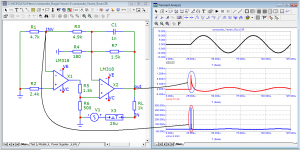
In this picture above the energy needed in (for an example) a feedback loop is still delayed 4 ms. Sure, you can see that the wave starts and stops at the same time but we need both volt and current at the same time to be able to do work (control an amplifier output stage driving a highly reactive load). Here the first initial peak does not give the feedback loop any potential to control the output due to the delay in total energy content - which peaks at the trailing end of the signal wave while it is needed at the leading edge. This is 4 ms delay of available energy - not voltage - needed to do its thing (in my view).
In this picture above the energy needed in (for an example) a feedback loop is still delayed 4 ms. Sure, you can see that the wave starts and stops at the same time but we need both volt and current at the same time to be able to do work (control an amplifier output stage driving a highly reactive load). Here the first initial peak does not give the feedback loop any potential to control the output due to the delay in total energy content - which peaks at the trailing end of the signal wave while it is needed at the leading edge. This is 4 ms delay of available energy - not voltage - needed to do its thing (in my view).
Why all the focus on theory?
The initial claim was that amplifier response to an non-audio frequency test stimulus has been found to correlate well with perceptual sound quality. That could be true, but for reasons having nothing to do with the basic theory being argued.
In that case the usual objection switches to an argument of, "if the amplifier was well designed," then the OP's original observation would not be true.
Not so fast, though.
What one assumes constitutes well-designed-enough might be turn out to be not really 'enough' in some real world situations. Particularly so for some listeners. I was struck by Hans Polak's recent description of seeing colors differently in each eye, but neither eye was color blind. As humans, we tend take as given that we see colors as they truly are and hear sounds as they truly are. We don't. And, we're all different in that respect.
Some people may hear audible problems with what some other people believe are perfectly well designed amplifiers. A particular stress test may correlate well for them. Why not?
May, might, could... As long as there's no real effort by people who can clearly hear these imperfections in an amplifier to use measurements and try to correlate the heard with the measured parameters there will be no path forward.
Several test stimuli for the DUT (amp) have been suggested (ragged sine wave, square, noise, music) and have been used to assess the quality of amps. But as long as these cannot be correlated in a meaningful way to proper listening tests we will still be around many many years from today discussing/babbling about all the same topic.
Several test stimuli for the DUT (amp) have been suggested (ragged sine wave, square, noise, music) and have been used to assess the quality of amps. But as long as these cannot be correlated in a meaningful way to proper listening tests we will still be around many many years from today discussing/babbling about all the same topic.
Thank you Jan for your great explaination with really clear and concise examples. 🙂
View attachment 900119
In this picture above the energy needed in (for an example) a feedback loop is still delayed 4 ms. Sure, you can see that the wave starts and stops at the same time but we need both volt and current at the same time to be able to do work (control an amplifier output stage driving a highly reactive load). Here the first initial peak does not give the feedback loop any potential to control the output due to the delay in total energy content - which peaks at the trailing end of the signal wave while it is needed at the leading edge. This is 4 ms delay of available energy - not voltage - needed to do its thing (in my view).
Are you aware what you are doing? You are inventing new stuff like 'feedback energy' to try to save your opinion which is wrong. Happens a lot - only very few people can make the jump and say - aha! I get it now!
Just keep thinking - you'll get it eventually ;-)
Jan
Last edited:
But this is sighted listening by someone who believes in the problem so not a valid data point.Why all the focus on theory?
The initial claim was that amplifier response to an non-audio frequency test stimulus has been found to correlate well with perceptual sound quality.
As humans, we tend take as given that we see colors as they truly are and hear sounds as they truly are.
I've not taken it as given since I was about 9 and was the only kid in class with glasses. It did take science a long time to accept that tetrachromic individuals exist mind.
Are you aware what you are doing? You are inventing new stuff like 'feedback energy' to try to save your opinion which is wrong
I am not inventing anything. I am pretty certain that "Volt X Current = power" is something someone has come up with before me... I am just stating that if phase is a difference between voltage and current being separated in time by a reactive element like a capacitor or a inductor, then in the example above there will be a 4 ms delay between when the feedback loop would need to control the output stage and when the feedback loop actually manages to control the output stage.
If there is no delay in energy in the LTSpice example above, what does the 4 ms in the simulated graph show? Why is the green curve still at -1 volt when the blue curve is at a full +1 volt? Is this not a lag of energy?
According to your comment
then I guess I just invented passive crossovers then?!? Can I have royalties for every speaker, radio or other electronic device that uses phase to make a frequency dependent roll of of energy by separating voltage and current in the time domain? Or are passive cross overs just something that I just made up to "save my opinion"?Are you aware what you are doing? You are inventing new stuff like 'feedback energy´
- Home
- Amplifiers
- Solid State
- First cycle distortion - Graham, what is that?