I read somewhere that an unbypassed cathode resistor means a dramatic change in the internal resistance of the tube compared to bypassed (but I can't remember which way it goes).
I have played with the bias on 6N1P until I am blue in the face, and I haven't found a plate current or load that I am completely happy with. Even without any real test equipment, I can tell by listening that there is some distortion there. A 6N3P seems to sound better in the same circuit (but it is a complete socket rewire job, so comparisons take some time). At least the mu is similar (36 vs 33), so NFB changes are probably not required. I would love to see spectra of the two of them under similar operating conditions.
I ordered 10 6N3P=EVs off ebay to try, although from the one data sheet I've seen they don't look as linear as the 6N1P-EV to me.
What bias conditions are you proposing? What type of bias?
Cathode Resistor, bypassed or un-bypassed?
LED cathode bias?
What plate load?
The Russian pdf data sheet for the 6N3P (not -EV) I have is 148kb in size for comparison to yours. I do have another sheet, but it's in Djvu format and 1.1Mb. It is however much more detailed in its curves.
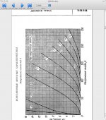
If you look at unbypassed cathode resistor bias of around -2v for a B+ of 250v and any load from 25k to 68k it looks pretty linear, but I have run a 220k load and it still sounded good (defying the characteristic curves). That's if I'm reading the curve correctly. To my mind that makes it a good candidate for a front end.
It looks very good with a CCS of about 4 to 6mA as well, but I haven't tried that yet.
I have tried IR LED bias of -1v and again it sounded much better than the curve would suggest.
To my ears (remember I don't have any other distortion measuring equipment) bypassing the cathode in either case either made no difference (Rk) or actually sounded worse (LED). However, the capacitor I used was just a junkbox one.
The 6N1P only really seems to improve when the available B+ is cranked toward the 400v end so I can get enough current through the tube at a sensible load. Ian found the same thing when we were doing the Mengyue Mini experiments.
However, it may be a good candidate for a CCS plate load, and that is on my list to try.
I am running a 6N1P with a plate load of 22k B+=250v and about -1.3v (bypassed Rk) bias in my 6P1P SE computer amp at the moment and it actually sounds quite good. Again, the curves say it shouldn't be very linear at all.
I've been using this one:
http://klausmobile.narod.ru/td/data/_6n3p.GIF
My latest testing has been with LED bias combined with CCS plate load, and may to some degree account for my liking the 6N1P(EV).
Just got back from Nasheville TN (Flooding) last night with our son, and I haven't had a chance to do anything in the shop today.
The 6N3P-EBs came in today, but it's going to be a couple of weeks before I can get back to the workbench. What operating point are you proposing to run at?
Right now the work bench is covered with engine parts from my 1975 Harley Davidson that I took apart to fix a low compression problem back in Feb. 2009 and never put back together.
I ended up tearing it all the way down and split the cases to install a new connecting rod set and rebuild it from the bottom up after I found a SS cam shim got chewed up by the cams and pumped through the engine.
I just looked at a schematic I drew when I used the 6N3P-EV to drive EL84 in class A SE.
I had a 47k plate resistor and a IR LED for bias of 1.05v, and B+ was around 280-300v from memory (I forgot to write it on the drawing, sorry). I think I ended up with about 2.5mA plate current.
Bear in mind, this was the input tube for an amp to suit my Mac Mini computer which has a low AF output level (<500mV).
It would be interesting to see how it responds to a CCS plate load.
I'll try it with a CCS plate load and LED bias. If I make the CCS variable I can try different current settings to see how it behaves.
With luck the son and I will have the engine off the workbench this weekend. I'm messing with RK (Road King) air shocks right now.
With luck the son and I will have the engine off the workbench this weekend. I'm messing with RK (Road King) air shocks right now.
I think I found some old HP IR LEDs I can try as well. They measure from 1.04 to 1.14V.
My B+ is a bit lower than yours, so I'll can use the HP supply on it and crank it up.
My B+ is a bit lower than yours, so I'll can use the HP supply on it and crank it up.
Gimp,
Very interesting experiments, really enjoying reading the thread. A few notes/observations if I may, hope its OK.
The only 6P1P-EV's I've seen on ebay or bought myself are NOS Svetlana. The Chinese made 6P1, not sure if they are still in production or not, some NOS are from the Beijing factory pre 1986 I think, now closed down/moved, and later ones are from the Shuguang plant. They have different markings.
It is good to hear you are still trying LED's as cathode load on the output tube. They are very difficult to work with, as the LED array needs to be designed for a specific current at a specific voltage and they do not bend. If the B+ happens to rise on the mains, the LED's will sink more cathode current and hold the bias voltage fairly constant. They are not forgiving nor adjustable, but fitting them to the Mengyue and a Simple PP gave similar results, deeper bass, more clarity, quite remarkable. I see you were interested in the RLD thread where some solid state circuit replacements for LED arrays were suggested by you and Wrenchone. Have you tried a listening test between LED's and your suggested cct? Such a cct, if it matches LED performance, would be brilliant. I don't know how LED's compare to fixed bias however, I wonder if the benefits of LED arrays are exactly the same as running fixed bias? Why is everyone (as in the tube forum) so quiet about this? I mean, if fixed bias was the ducks nuts, then LED arrays would not be in existence. I bought some parts to try fixed bias in the EL84 amp, and am really keen to try a transistorized cathode load also, (using just my ears to judge). The benefits of a transistorized cathode load is the ability to adjust the bias voltage and therefore cathode current, instead of buying 100 or 200 LED's to get an array happening after matching every individual LED to make equal strings of equal current and voltage etc etc etc, 10 hours later....the only way to adjust bias with LED arrays is with screen current regulation or simply combination bias where you use the LED array and fixed bias with pots to adjust the grid voltage. If you go that far mosfet source followers are not much trouble to add (another good one, if you are in the mood for extra clarity). If fixed bias was good, you would just do fixed bias, and forget all the other stuff.
I have not found any considerable difference in sound quality between the 6P1P-EV and JJ EL84 tubes. EL84 seems to make more power more easily, which might explain why its popular.
That Klausmobile site is wonderful.
Tube List (English)
Tube Tester Files - 6N1P - 6H1?
Tube Tester Files - 6N3Pi-E
Glad to hear that HP supply is coming in handy 🙂
Edit: the "3mA / 120V closeup" on the 6N1P answered many questions for me.
Last edited:
Thanks Ian, constructive criticism is always welcome.
I'm just trying to learn so I do a lot of experiments. Simulations are interesting and can lead to good insight, as well as studying formulae and theory, however they are all apporximations of what the tubes actually do.
I really would like to understand tube operation to the point where I could modify the tube models for some of the russian tubes to get them to more closely match the real world, but getting the time is another matter.
The "3mA / 120V closeup" is indeed interesting. I usually go to the Klausmobile site first for data on Russian tubes (probably should call them Soviet rather than Russian as there were many tube mfgs and all were not in Russia propper).
I think the issue of Fixed Bias vs cathode bias is a matter of circuit complexity and how many power supplies do you need.
However, cathode bias does tend to provide some small amount of NFB as most cathode devices will increase voltage drop with increased current flow (except ideal LEDs, Vshunts, etc). This small amount of NFB helps stabalize the circuit. This is not true with fixed bias, and hence makes it more sensitive to voltage variation and less stable.
I would really like to try the same amp with different bias mechanisms at the same operating point and measure changes in distortion, then do listening comparisons. It will be difficult to switch between them on the fly though, and it would require switching bias to two tubes at the same time if a PP amp were used. SE might be easier in this regard.
My experiments with screen control of bias indicated that it is feasable, but possibly only over a very narrow range and may not compensate for large variation in tube parameters without causing increased 2nd harmonic distortion due to compression of the curves. This is unfortunate as it looked like a good cantidate for bias adjustment with cathode bias.
I'm beginning to think this is like pushing on a balloon. Push in on one side and the rest just shifts to take up the change. We try to achieve static bias to null the load current through the transformer, but in the process we shift the plate curves and change the gain of the tube. So we are statically matched, but not dynamically matched which results in increased distortion.
If instead we adjust the dynamic matching and leave the bias through the transformer to shift, we effect the B-H curve positionand have a particular effect on low frequency distortion.
It almost requires two mechanisms to (1) adjust static bias current, and (2) adjust the plate curves to match for matched gain and minimum distortion. In class A this is not as critical, but I think that in AB1 it will really cause problems as one tube shifts into B operation while the other is in A operation. Missmatched tube characteristics will result in miss matched gain of opposite phases of the waveform. Thus higher 2nd order harmonic distortion.
Thanks Ian, constructive criticism is always welcome.
Sorry if it came across as any sort of criticism. It was more my musings of how I use LED's... I am keen to hear any audible results of your transistorized bias cct vs LED's when/if you get around to doing that. I am very tempted to try it, and compare LED's to transistorized bias to fixed bias.
However, cathode bias does tend to provide some small amount of NFB as most cathode devices will increase voltage drop with increased current flow (except ideal LEDs, Vshunts, etc). This small amount of NFB helps stabalize the circuit. This is not true with fixed bias, and hence makes it more sensitive to voltage variation and less stable.
I think with LED's there is still some local feedback through the cathode. With my Meng 6P1 PP, with 7.6V rms sine going into the grid, I measured 0.55V rms sine at the cathode. This seems a lot of FB to me, but my theory is limited, so I don't understand how significant it is. I just wonder if the quality or speed of local feedback from LED's is more accurate than that from a resistor/capacitor combination? The LED's do suffer the same drawbacks as fixed bias that you mention.
Good luck with your experiments, always a good read. I'm a bit behind the eight-ball in theory and test equipment but tinkering along regardless...
Didn't mean to imply you were criticizing me, probably a bad choice of words. I'm just open to discussion.
No time to work on it this weekend. Got a little done on the bike and spent most of the time helping family.
No time to work on it this weekend. Got a little done on the bike and spent most of the time helping family.
I have 2 Buells and a spare (broken) motor, hope your Harley gets back on the road soon for the warm weather.
I'm trying a Baby Huey type circuit next, see what happens.....
I'm trying a Baby Huey type circuit next, see what happens.....
Last edited:
I finally got around to doing some testing of the 6N3P compared to a 6N1P.
I'll do more, but I did some preliminary testing with 250V plate supply, adjustable current source plate load, and LED cathode bias.
I adjusted the cathode current source for the lowest 2nd harmonic distortion as seen on AudioTester V3 and then measured the distortion with the HP 333A.
Cheap red LED and 87 Ohms series resistor (set up for feedback from transformer output, but no feedback present). 2.1V cathode voltage:
6N1P Va=137V 0.44%thd
6N3P Va=155V 0.88%thd
I then tried a lower voltage LED (IR) with 1.5V on the Cathode, no series resistor.
6N3P Va=155V 1.38%thd
Opto Interrupter IR LED, Vk=1.156V:
6N3P Va=155V 1.71%thd
300V B+ with Opto Interrupter IR LED Vk=1.98V:
6N3P Va=155V, 1.77%thd
Preliminary conclusion is that the 6N1P is lower in distortion, but has less gain (1:1.4) compared to the 6N3P.
The 6N3P produced the lowest distortion with the higher bias (2.0V vs 1.5V and 1.15V).
Increasing B+ did not reduce distortion by allowing operation in a higher bias area.
Based on discussions about soviet 6L6GC (6P3S) I'm wondering if I need to 'cook in' the tubes before doing such testing. The 6N1P probably has 20hrs of operation compared to the 6N3P only about two hours.
Still need to work on the Harley.
I'm thinking about using some Schade feedback on the next PP I build. Probably not BH though.
Last edited:
OK, I think I figured what is going on. The distortion is an order of magnitude lower, and my measurement technique is faulty.
1) I need to buffer the triode output or I load it down differently when I hook up the HP333A vs the sound card input with AudioTester V3.
I used the spare triode in each tube as a cathode follower with a 15K cathode resistor and direct coupling to buffer the first triode and got rid of a lot of voltage variation from loading.
Is this acceptable? Would a FET source follower be a better choice as I could use the same type FET for both tubes and eliminate some variations?
I had to use a 15K grid-stop resistor from plate to grid on the 6N3P to prevent oscillations. It was not necessary with the 6N1P.
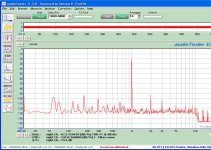
2) Most of the distortion I was measuring has nothing to do with the 1KHz test signal. It is caused by the 60hZ (and harmonic) noise that is picked up either from the PS or airborne because of wiring.😡
6N1P FFT
6N3P FFT
So now I need to clean up the ps or find the source and eliminate it before I can take measurements that make sense.
On the other hand, Audio Tester V3 shows the 60Hz component and when I plug the value into my distortion spreadsheet it is close to the value I measure with the HP333A. So the two tools together do show what is going on.
I tried increasing the B+ up to 300V again but still didn't see much difference over 250V with the IR diode and Current source on the 6N3P.
1) I need to buffer the triode output or I load it down differently when I hook up the HP333A vs the sound card input with AudioTester V3.
I used the spare triode in each tube as a cathode follower with a 15K cathode resistor and direct coupling to buffer the first triode and got rid of a lot of voltage variation from loading.
Is this acceptable? Would a FET source follower be a better choice as I could use the same type FET for both tubes and eliminate some variations?
I had to use a 15K grid-stop resistor from plate to grid on the 6N3P to prevent oscillations. It was not necessary with the 6N1P.
2) Most of the distortion I was measuring has nothing to do with the 1KHz test signal. It is caused by the 60hZ (and harmonic) noise that is picked up either from the PS or airborne because of wiring.😡
6N1P FFT
An externally hosted image should be here but it was not working when we last tested it.
6N3P FFT
An externally hosted image should be here but it was not working when we last tested it.
So now I need to clean up the ps or find the source and eliminate it before I can take measurements that make sense.
On the other hand, Audio Tester V3 shows the 60Hz component and when I plug the value into my distortion spreadsheet it is close to the value I measure with the HP333A. So the two tools together do show what is going on.
I tried increasing the B+ up to 300V again but still didn't see much difference over 250V with the IR diode and Current source on the 6N3P.
Elevating the filaments to 75V wrt cathode got me to -75db at 60hZ. Harmonics are still around the same level though.
I didn't expect to see this kind of harmonic content from the HP 6448V this lightly loaded. Especially after going through two RC filter stages in the B+ line.
I didn't expect to see this kind of harmonic content from the HP 6448V this lightly loaded. Especially after going through two RC filter stages in the B+ line.
I tried :
line filters to the B+ and filament supplies.
Isolating grounds.
Rewiring the filaments.
DC power supply for filaments.
Switching to a different HV power supplie.
and I'm at my witts end.
I get a 40db jump in floor noise every time I power up the amp.
I'm going to run a new feed from the circuit breaker box to make sure I have a good ground, and check all outlets on the work bench. If it isn't a ground loop causing it I don't know what it is.
As is, I can't get good distortion measurements due to the 60hz interference and its harmonics.
One can see in the last plot that the unused channel noise floor is near -140dB, but the noise floor of the used channel is about 40dB above it with 60hz and harmonics all the way up to -60dB. I've switched channels and the problem switches so it is not the sound card, and most likely not hte computer the sound card is in.
If rewiring the AC mains does not fix the problem, I'll start a new thread on noise problems and interference in testing to see if someone can give me some ideas.
I may set up an isolation transformer for a second power strip while I rewire the mains line.
Well, I replaced the 12-2 w/ ground and added a second circuit breaker and second run of rohmex 12-2 w/ ground and now have two circuits available on the steel support pole next to the work bench. I didn't install the isolation transformer yet.
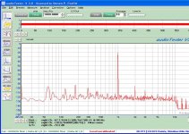
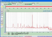
I ran a plot of the test amp and the new power runs reduce the 60Hz fundiamental slightly, but not the harmonics and the rest of the garbage.
On a lark, I changed tubes and plugged in a 6DJ8. What an amazing difference!
So what is all the garbage with the 6N1P and 6N3P tubes?
The 6N3P oscillated but I added a gridstop resistor and cleaned that up.
I'm also trying to figure out what the source of the 10.5KHz blip is. It is present in all plots but I have no idea where it is coming from.
I ran a plot of the test amp and the new power runs reduce the 60Hz fundiamental slightly, but not the harmonics and the rest of the garbage.
An externally hosted image should be here but it was not working when we last tested it.
On a lark, I changed tubes and plugged in a 6DJ8. What an amazing difference!
An externally hosted image should be here but it was not working when we last tested it.
So what is all the garbage with the 6N1P and 6N3P tubes?
The 6N3P oscillated but I added a gridstop resistor and cleaned that up.
I'm also trying to figure out what the source of the 10.5KHz blip is. It is present in all plots but I have no idea where it is coming from.
I think one of my power strips is partially to blame for the problems I've been having with taking good distiortion measurements and seeing a lot of floor noies.
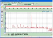
I eliminated one last night and got a cleaner measurement. The suspect power strip is 30 years old (TI surplus).
I'm still seeing too much 60Hz and harmonics from it. The plot is without ground hooked to chassis on the test amp. If I hook green wire ground from a power plug to chassis I get about 20db more 60hz and associated harmonics.
I finally cleaned up enough noise to get below 1% THD. The HP333A shows 0.9%THD now. The 60Hz harmonics are still a good portion (more than 50%?) of that so I still can't get an accurate measurement for comparison testing with the 6N3P.
I still haven't found the 11KHz noise source either, and may resort to switching off breakers one at a time till I find which breaker it is on, then look for it. Although it is now down below -100dB and may not be significant.
I did NOT find a ground rod at my utility box. There is one on the power pole, but it is over 100M away. I'm hoping i'm wrong, as I don't relish the thought of driving a 10' ground rod in red clay soil. I'll take another look today and clear out the corner of the garage below the breaker box in case the ground rod is hidden by all the lumber in the corner. If it is there, I will verify good continuity, and water it.
I eliminated one last night and got a cleaner measurement. The suspect power strip is 30 years old (TI surplus).
I'm still seeing too much 60Hz and harmonics from it. The plot is without ground hooked to chassis on the test amp. If I hook green wire ground from a power plug to chassis I get about 20db more 60hz and associated harmonics.
An externally hosted image should be here but it was not working when we last tested it.
I finally cleaned up enough noise to get below 1% THD. The HP333A shows 0.9%THD now. The 60Hz harmonics are still a good portion (more than 50%?) of that so I still can't get an accurate measurement for comparison testing with the 6N3P.
I still haven't found the 11KHz noise source either, and may resort to switching off breakers one at a time till I find which breaker it is on, then look for it. Although it is now down below -100dB and may not be significant.
I did NOT find a ground rod at my utility box. There is one on the power pole, but it is over 100M away. I'm hoping i'm wrong, as I don't relish the thought of driving a 10' ground rod in red clay soil. I'll take another look today and clear out the corner of the garage below the breaker box in case the ground rod is hidden by all the lumber in the corner. If it is there, I will verify good continuity, and water it.
Well Ian, hopefully I've come full circle.
I think I finally have my measurements in order.
I ran the 6N3P with a IR LED and current source in the anode ckt. I adjusted the current and monitored the anode voltage from 80V to 120V while taking FFTs. The minimum distortion was around 90 to 100V on the cathode. I did not measure the current as this would have required a sense resistor either in the anode or cathode circuit.
Here are the plots for 80, 100 and 120V, along with the 6N1P at 120V(last plot):
The 6N3P seems to do best around 110V Va. The 6N1P is a little lower in overall distortion but needs about 10V more across the tube. I don't think the difference is significant in terms of measurements. I have not done listening tests yet but hope to do some later in the week.
One observation. If using a current source for the anode load, increasing the anode supply has no effect. The current source simply drops the additional voltage with no effect. This makes sense when one thinks about it.
Attachments
- Status
- Not open for further replies.
- Home
- Amplifiers
- Tubes / Valves
- FireFly Single Ended Tetrode