Tony, I wasn't complaining about the ST optical o/p at all. It's good to have a pcb hosting all possible interfaces. You can chose the one/ones you prefer.I understand massimo's preference, but I do hope for a ST solution. Many older higher end DACs used ST glass. It's a much better interface than Toslink (for those who can use it).
P.S. Toslink is the worst by far IMO
No problem massimo! 🙂 I expect the number of people interested in ST would be small, so I just wanted to express my interest one more time. 😉
BTW Tibi, for coaxial out please tell us you're looking at a BNC output. Regardless of what some may wish to consider (or believe) there is no such thing as an RCA connector which exhbits a true 75 Ohm characteristic impedance. Not physically possible. I'd suggest getting the design correct at the interface; users can get a BNC-RCA adapter if needed.
BTW Tibi, for coaxial out please tell us you're looking at a BNC output. Regardless of what some may wish to consider (or believe) there is no such thing as an RCA connector which exhbits a true 75 Ohm characteristic impedance. Not physically possible. I'd suggest getting the design correct at the interface; users can get a BNC-RCA adapter if needed.
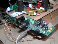
BMW850, that looks very sweet. Is there a link which points to Erik discussing what he did here?
I see he also decided to go with BNC. Nice!
I see he also decided to go with BNC. Nice!
Look here: http://www.diyaudio.com/forums/digi...ordable-cd-transport-shigaclone-story-52.html
Regards,
Rudy
Regards,
Rudy
Have some information found do not know whether it is usable.
Regards,
Rudy
Regards,
Rudy
Hi Valo,
The outputboard is from Wadia 22/23.
On this board the AM26LS31CN chip is fitted followed by a CTS ODL 50 series 2 for ST-optical.
The AM26LS31 is pin compatible with DS26LS31.
Anton.
I appreciate that we are trying to improve over the original, and having extra options to choose from is certainly great. But still, the most common digital interface (by far) is SPDIF over RCA, so I would propose to keep this as our "basic" solution. I heartily support Tibi's proposal to design an extra (optional) PCB for all the more exotic connectors and reclocking.
I would like to reiterate my appeal to try to keep this project friendly to the less skilled DIYers, and also reasonably cheap. There is nothing to stop us from designing a new player after this one, with some much more advanced solutions, or hardcore choices.
I would like to reiterate my appeal to try to keep this project friendly to the less skilled DIYers, and also reasonably cheap. There is nothing to stop us from designing a new player after this one, with some much more advanced solutions, or hardcore choices.
Seperate boards
 Just to chip in and say that I found separating the boards very beneficial...
Working on my mark II 'classic' clone (silly I know) which has the original black gate configuration. In truth I can't comment on the improvement in sound since too many other factors are also different from my Mk I attempt.
CD Transport (Shigaclone) Version 1, 2011 twiddlingmyknobs
I am using cast iron for the base, it has very good vibration damping properties...
SPDIF output for me since I need to keep it simple... more options sounds good though!
Just to chip in and say that I found separating the boards very beneficial...Working on my mark II 'classic' clone (silly I know) which has the original black gate configuration. In truth I can't comment on the improvement in sound since too many other factors are also different from my Mk I attempt.
CD Transport (Shigaclone) Version 1, 2011 twiddlingmyknobs
I am using cast iron for the base, it has very good vibration damping properties...
SPDIF output for me since I need to keep it simple... more options sounds good though!
Last edited:
I like your solid design and (equally solid) parts choices, billo44. Where did you get that cast iron base?
I appreciate that we are trying to improve over the original, and having extra options to choose from is certainly great. But still, the most common digital interface (by far) is SPDIF over RCA, so I would propose to keep this as our "basic" solution. I heartily support Tibi's proposal to design an extra (optional) PCB for all the more exotic connectors and reclocking.
I would like to reiterate my appeal to try to keep this project friendly to the less skilled DIYers, and also reasonably cheap. There is nothing to stop us from designing a new player after this one, with some much more advanced solutions, or hardcore choices.
I'm of two minds about this, uncle_leon. While I appreciate and agree with your statement about keeping this DIY friendly and in keeping with the original concept, history often shows that the "next, enhanced version" sometimes never comes to pass. Given how long it's taken for Peter's (and others') brainchild to come to its current state, I'm not sure a subsequent version with this extra capability will ever have the same momentum behind it.
I would offer that if this base design is considered good enough to be used as a foundation for its own improvements, any such improvements should be considered within the context of being able to fit into said design. If it can be done in a way that allows for these features to be incorporated as desired then I think it will keep the DIY-friendly aspect intact. But such improvemnts may wish to be considered now to see if it will require small perturbations to the current design, to allow for later implementation.
As for RCA out, yes it is the most common interface. Perhaps if there were a way to fit the PCB with the pin and pitch layout for either RCA or BNC it would then leave the builder with the opportunity to fit the interface to support their need? It would then allow for a proper 75 Ohm output to be inherent on the board. For sizing purposes I'd recommend something like an Amphenol 031-70221.
I see what you are saying, tonyptony, and you do have a point.
Another thought has just occurred to me - why any connectors should be mounted on the control PCB in the first place? Most people, I suspect, will prefer to have the connectors mounted to their cases - hence my proposition is, let's leave the digital output "bare", similar to what we had with the original Shiga. The choice (and wiring) of connectors will be then up to the constructor.
Another thought has just occurred to me - why any connectors should be mounted on the control PCB in the first place? Most people, I suspect, will prefer to have the connectors mounted to their cases - hence my proposition is, let's leave the digital output "bare", similar to what we had with the original Shiga. The choice (and wiring) of connectors will be then up to the constructor.
That sounds reasonable. As long as it can be done in a way that would not compromise the ability to get a true 75 Ohm signal path to the back panel. I expect AES/EBU Type I could be done the same way. Optical of either sort would have to be board mounted, I think.
If this is a laser/Diode output, and not the receiver photo-diode/phototransistor, shouldn't it be relatively insensitive such that a section of something like RG-174 wold be sufficient as long as one was talking about a couple of inches (<6" / <15cm)?
hi,
I put a jvc rcez 31 on ebay,I didn't want to sell it ,but need the cash,I hope someone will enjoy it and forgive me mods for posting it here but I thought everyone would see it here,Thanks
http://www.ebay.com/itm/120872864639?ssPageName=STRK:MESELX:IT&_trksid=p3984.m1555.l2649
I put a jvc rcez 31 on ebay,I didn't want to sell it ,but need the cash,I hope someone will enjoy it and forgive me mods for posting it here but I thought everyone would see it here,Thanks
http://www.ebay.com/itm/120872864639?ssPageName=STRK:MESELX:IT&_trksid=p3984.m1555.l2649
I prefer BNC as well, the others might be optional. I also support the idea of having the PCB on its own.
Brgds
Brgds
The board we are currently designing will have digital output only trough a small PCB connector.
Is up to end user which connector will use.
The reclocking board who will support all possible connectors and interfaces: BNC, XLR, RCA, TOSLINK, AT&T ST glass is part of this project, but we´ll design this later.
A lot of investigation need to be done on the reclocking circuit, AES/EBU trafo, Toslink and especially on AT&T ST glass.
Some extensive tests and measurements need to be done as well.
Therefore this board will come later to complete this project.
Thanks & Regards,
Tibi
The board we are currently designing will have digital output only trough a small PCB connector.
Is up to end user which connector will use.
The reclocking board who will support all possible connectors and interfaces: BNC, XLR, RCA, TOSLINK, AT&T ST glass is part of this project, but we´ll design this later.
A lot of investigation need to be done on the reclocking circuit, AES/EBU trafo, Toslink and especially on AT&T ST glass.
Some extensive tests and measurements need to be done as well.
Therefore this board will come later to complete this project.
Thanks & Regards,
Tibi
Thank you Tibi. That's good enough for me. Can you tell us what the PCB layout and spacing is for the board mounted connector?
- Home
- Source & Line
- Digital Source
- Finally, an affordable CD Transport: the Shigaclone story