Are we sure that the "CD Stop SW" is really needed? When we buy a Sanyo CD mech on eBay it comes with a small pcb for sw and motors to be connected via a 2 mm pitch 6 pole connector to the main pcb. The mech/pcb found in the boombox is a different story.
SF-P101N CD Mechanism SFP101 16 Pins Sanyo Philips Alba | eBay
As I said above, this switch need to be moved to the board we are designing now and must be placed in exact same place.

We need to make a library with precise dimensions to match leaf-switch design.
Regards,
Tibi
Last edited by a moderator:
Keeping the small pcb and sw on the mech and connecting it to the new main pcb, not only offer Jazz more freedom in designing the pcb, but also isolates the motors from the electronics. Somebody in the past reported this as beneficial sound wise.
It's an option I would consider......
It's an option I would consider......

Keeping the small pcb and sw on the mech and connecting it to the new main pcb, not only offer Jazz more freedom in designing the pcb, but also isolates the motors from the electronics. Somebody in the past reported this as beneficial sound wise.
It's an option I would consider......
I'll be glad to adopt this design approach. 🙂 What about the owners of the original JVC-board???
Also, this approach means that the main board will no longer be fixed on chassis.
J
Last edited:
Keeping the small pcb and sw on the mech and connecting it to the new main pcb, not only offer Jazz more freedom in designing the pcb, but also isolates the motors from the electronics. Somebody in the past reported this as beneficial sound wise.
It's an option I would consider......
I completely agree with you that keeping the board away from motors will bring some benefits.
On the other hand, I would prefer to keep the cable path from optics to ASP chip as short as possible.
If I put in balance the best option looks to me a short path to optical.
What is your opinion ?
Regards,
Tibi
I have also separated the board from the engine and use also the short laser cable, that is no problem 😉
Regards,
Rudy
Regards,
Rudy
I have also separated the board from the engine and use also the short laser cable, that is no problem 😉
Regards,
Rudy
Rudy,
Can you post a picture please ?
I´ll discuss with jazz35 all implications for a separate board and come back tomorrow with a conclusion.
In the mean time I would like to hear others opinion.
Regards,
Tibi
The flat cable from the laser assembly must be kept short, I totally agree.
Let's consider the boombox original pcb: a cheap single sided pcb plenty of 0805 smd jumpers. If you were going to make 100.000 pcbs, this kind of product allow to save some pennies, but for 100-200 pcs a double side FR4 pcb would cost more or less the same and I'm pretty sure this is what you have in mind. With a double side pcb you save a lot of jumpers (and space), you don't have to consider the motors/sw positions and footprints, etc. All in all it can be kept smaller than the current one, so small to be placed underneath the Sanyo mech and its small pcb without increasing the length of the flat cable. The only drawback is that the player will result 1 cm (or so) higher, but I personally don't consider this a real problem.
Let's consider the boombox original pcb: a cheap single sided pcb plenty of 0805 smd jumpers. If you were going to make 100.000 pcbs, this kind of product allow to save some pennies, but for 100-200 pcs a double side FR4 pcb would cost more or less the same and I'm pretty sure this is what you have in mind. With a double side pcb you save a lot of jumpers (and space), you don't have to consider the motors/sw positions and footprints, etc. All in all it can be kept smaller than the current one, so small to be placed underneath the Sanyo mech and its small pcb without increasing the length of the flat cable. The only drawback is that the player will result 1 cm (or so) higher, but I personally don't consider this a real problem.
Absolutely! This is the beauty of this forum!.
In the mean time I would like to hear others opinion.
Let's wait for our friends on the other side of the globe when they will wake up.... 😉
Read this, also an picture of Erik site.
Regards,
Rudy
Just got my RCEZ31. My first impressions:
RCEZ32 (the one kevink talks about) has a better DSP chip (and one much closer to original Shig) than the RCEZ31 (which benefits/suffers from Sanyo's integration program which is meant to reduce chip count for low-end designers).
The fact that LC78601RE has to devote significant die space to an integrated u-controller w/ display block, lcd driver, and control processing means corners were cut in other areas and RFI interference between the blocks will be more common. I would rather see the influence of the display and control processing in the signal-processing block minimized by separate physical location, supplies, and decoupling of two separate packages. U-controllers are some of the nastiest sources of noise in a digital system...
On the other hand, what is nice about the RCEZ31 (and which improves on Shig even) is the connection between laser pickup and ASP is made as short as possible, with the ASP located directly under the laser sled. Note however that reducing the distance here increases the influence of spurious radiation and cares should be taken to shield the two blocks with shield lines or anti-EFM material (in early Flatfish it was a ground shield around the eight-lead harness carrying the pickup photodiode and track error signals). Note also that the direct connection between main pcb and laser sled mechanism means that there will be mechanical disturbances created by the servo motors on a pcb stuffed with microphonic ceramic chip caps and digital ICs. I would strongly advice detaching the pcb from the laser sled assembly, and making the connection to the motors via short wires, rather than letting the motors have their ways with that pcb. I would also recommend removing that plastic housing guard over the laser pickup--less is better here--and (unlike 47 Lab Shig) mounting adjustable spikes for the CD player directly on the four stand-offs that support the laser assembly unit, with some added mass, rather than spiking a traditional chassis at some point located a distance from the stand-offs or placing the whole thing on some wood/metal/ceramic plinth. The resonances from the CD mechanism need to leave it as directly as possible, and there is no more direct route than the stand-offs. Also, the manufacture of a precise delrin platter/clamp which fits tightly to the motor shaft without need of any bonding substance is also very desireable.
One thing: do not waste your time. The ASP and DSP will present a bottleneck in terms of spec and number, but have little to do with sound quality: I spent hours playing with different RF amp configs, and putting high-quality passive components into the PLL clock generation circuit (two years of tinkering with Caddocks and BGs on an old Flatfish, where the board was through-hole and parts were easy to swap) to no avail. Besides mechanical construction (which is very important), the biggest bottleneck for a system like this will be the supply regulation, grounding and decoupling. Indeed, some regulators are better tha others, and the 5V regulator sitting inside the MM1469 has at best 75dB rejection at 1kHz during steady state operation (they do anything to optimize their specs); during heavy servo operation, it is far worse, and there is quite alot of noise of all frequencies modulated into the 5V reg block, esp. during TOC and track skip operations. Being a linear reg means that it cannot filter out HF and RF noise, but passes it through: result is a white, bodyless presentation, without fundamental tones (my main criticism of 47 Lab digital players). I won't criticize JVC: budget is budget. It cost me Eu39! Their player is fast, and rhythmic. But the PSRR at 10MHz or at 100MHz is next to nil. The noise will get into your chips, get stored in parasitic capacitances, released a little later, generate offsets, modulate or be modulated by your RF digital signals, generating all kinds of intermod products, noise modulations, etc. etc. My advice: Do not use MM1469 as your final reg. Using the LM7808 as a pre-reg for the MM reg is only half a solution. Using a low-noise, low-output-impedance 5V reg with good dynamic performance (like the ALWSR super-reg or other) for your ASP/DSP combo (and another separate one for the internal 1-bit DAC if you are using the analogue out option) while adding some series resistance before good local decoupling will suprise you even further how good this chip combination can sound.
Attachments

Last edited:
I agree that isolating the board from the motors is important. One question in my mind is how far is far enough?
An additional idea is to add a Mu-Metal shield between the motors and the board. I don't see that any spacing option would preclude this.
How good is the internal DAC option?
I was expecting to use an external DAC (WM8741) but it might be nice to compare the two for myself since I have no experience with such.
Keeping the small pcb and sw on the mech and connecting it to the new main pcb, not only offer Jazz more freedom in designing the pcb, but also isolates the motors from the electronics. Somebody in the past reported this as beneficial sound wise.
It's an option I would consider......
I'm definitely with massimo on that.
I don't quite see the point of discussing the length of the ribbon cable at this stage though (but maybe I'm missing something?...). The way I'm imagining it, we will have a "control PCB", which we will be able to connect to any compatible CD mech in any way we please - with a short ribbon, with a long ribbon, hard-wired or whatever. As BMW850 rightly pointed out, closer is not necessarily better, and some degree of separation will almost surely be beneficial. Everyone can decide for themselves how far to go with separating the two components when they actually build the player as there will inevitably be other constraints to consider.
@TheGimp - the internal DAC is ok-ish, but nothing to write home about... It has a fairly bright sound, mediocre bass control and a typical "digital" timbre.
Last edited:
I'm going to order 50 CD-mechanic SFP101N-16P-DA11V.
Tibi, is this the same mechanism which you are ordering?
SF-P101N CD Mechanism SFP101 16 Pins Sanyo Philips Alba | eBay
Oh, and while I know this will be of no real use to virtually anyone else, would anyone know just what it would take to fit a ST glass output to this design? I have two DACs (EAD and Wadia) and both have the ST glass input. Right now I consider that superior to others using my current transport. In my dream for this DIY project I'd love to be able to have a quality ST output available.
Last edited:
Thank you all for your opinions!
The benefits for having a separate board are obvious.
- less mechanical vibrations, less noise induced by ceramic components
- more space to accommodate 1206 components
- better layout and grounding as the motors are no longer on pcb
- flexibility in terms of board placement - dampening, shielding etc
Jazz and me will change the design for a separate board.
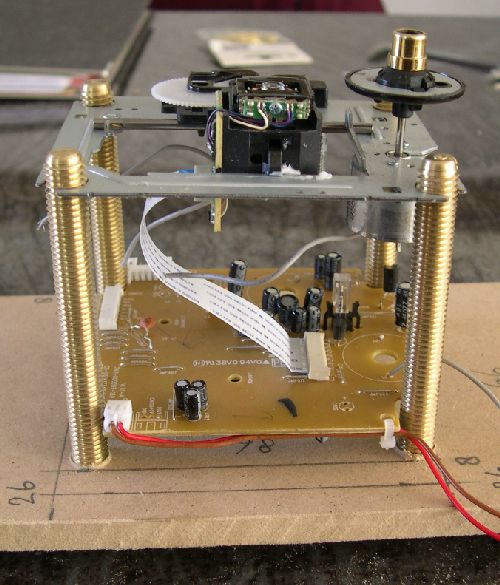
The board will be mounted under cd mechanic, something like in picture posted by Rudy http://www.diyaudio.com/forums/atta...ble-cd-transport-shigaclone-story-oil-rig.jpg
Regards,
Tibi
The benefits for having a separate board are obvious.
- less mechanical vibrations, less noise induced by ceramic components
- more space to accommodate 1206 components
- better layout and grounding as the motors are no longer on pcb
- flexibility in terms of board placement - dampening, shielding etc
Jazz and me will change the design for a separate board.
The board will be mounted under cd mechanic, something like in picture posted by Rudy http://www.diyaudio.com/forums/atta...ble-cd-transport-shigaclone-story-oil-rig.jpg
Regards,
Tibi
Last edited by a moderator:
Tibi, is this the same mechanism which you are ordering?
SF-P101N CD Mechanism SFP101 16 Pins Sanyo Philips Alba | eBay
Oh, and while I know this will be of no real use to virtually anyone else, would anyone know just what it would take to fit a ST glass output to this design? I have two DACs (EAD and Wadia) and both have the ST glass input. Right now I consider that superior to others using my current transport. In my dream for this DIY project I'd love to be able to have a quality ST output available.
Yes, it is the same mechanic.
ST glass output it is an option I´ll consider.
Maybe it will be another separate board with reclocking and AES/EBU, S/PDIF, Toslink and AT&T ST glass.
Do you have any recommendation here for a good ST glass output?
Regards,
Tibi
Last edited by a moderator:
Can be an option
Laser -> http://www.optekinc.com/datasheets/OPV314AT.pdf
LED TX -> http://www.optekinc.com/datasheets/OPF694.PDF
LED RX -> http://www.optekinc.com/datasheets/OPF560.PDF
And here an application note from HP
http://server.elektro.dtu.dk/ftp/da...98/pdf_docs/fiberopt/hispdic/05_apps/ab78.pdf
And an old thread http://www.diyaudio.com/forums/digital-line-level/140372-fibre-optic-t-style-hp-optek.html
Regards,
Tibi
Last edited by a moderator:
Very good idea, Tibi!Maybe it will be another separate board with reclocking and AES/EBU, S/PDIF, Toslink and AT&T ST glass.
I understand Wadia user, but I support AES/UBS over the rest.
Very good idea, Tibi!
I understand Wadia user, but I support AES/UBS over the rest.
Totally agree.
Can be an option
Laser -> http://www.optekinc.com/datasheets/OPV314AT.pdf
LED TX -> http://www.optekinc.com/datasheets/OPF694.PDF
LED RX -> http://www.optekinc.com/datasheets/OPF560.PDF
And here an application note from HP
http://server.elektro.dtu.dk/ftp/da...98/pdf_docs/fiberopt/hispdic/05_apps/ab78.pdf
And an old thread http://www.diyaudio.com/forums/digital-line-level/140372-fibre-optic-t-style-hp-optek.html
Regards,
Tibi
Many, option????
Wonderful, I agre!
Regards
Ivo-Cici
ST glass output it is an option I´ll consider.
Maybe it will be another separate board with reclocking and AES/EBU, S/PDIF, Toslink and AT&T ST glass.
Do you have any recommendation here for a good ST glass output?
Regards,
Tibi
No Tibi. I wish I did. My experience is only with the older ODL 50 types and one from HP.
I understand massimo's preference, but I do hope for a ST solution. Many older higher end DACs used ST glass. It's a much better interface than Toslink (for those who can use it).
- Home
- Source & Line
- Digital Source
- Finally, an affordable CD Transport: the Shigaclone story