i've also got another question
i am planning to replace all electrolytic caps in the shigaraki board with same value rubycon zl & zlh, caps mainly due to their higher ripple current value
i am going to use ruby's even in the ps too
an alternative option would be panasonic fc's throughout.
so effectively i am keeping the board "standard" but with better components. the only changes would be the addition of digital out resistors & removal of the ps choke
good idea? bad idea?
chatziva said:good idea? bad idea?
Could be potentially a bad idea. Don't change anything until you get familiar with the sound of unmodified board, only then start introduce chages, one by one. In spite of popular opinion, those caps on JVC board are pretty good quality and Rubycons are not neccessarily better.
The only caps I would recommend to replace are the ones directly at the regulators.
I use high power resistors, because that was the only size available for that particular type; 1/4 - 1/2W will work fine as well, in fact that's what I used in my most recent implementation.
mine are metal film 0.40W 1%. They seems to work well.Originally posted by chatziva has anybody tried low wattage ones such 1/4 or 1/2 W ? [/B]
o.k. - i have a question - nobody had a suggestion - so i am trying with the picture attached....
i was thinking about two options....
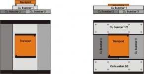
1. to put three copper bussbars in paralel with each other.....two of those on the "ground floor" and the third one on top of those two... and than to mount the mechanism on top of them - the total thickness of the copper where i will mount the mechanism will be here 20mm (each bussbar is 10mm thick)....
this option is on the left in the picture....
2. this option also has wo opper bussbars in the "ground floor" but the third one has been cut through the middle to form two separate bars - and than mount them in the front and in the back of the transport - in this case the mechanism is mounted on top of the "ground floor" and the two part of the third bussbar are here only to connect everything together and to make more weight to the whole thing....
as i have menioned - i have three bussbars that have a dimenisons 200*100mm and they are 10m thick..... so this will be used as a base for the mechanism 😀
one more question is - if i should connect upper floor bussbars with the ground floor directly or should i use something in between them - i have some subber, also some material that is in fact cork mixed with rubber - we use it in our company for the power transformers to seal the transformer from leaking oil.....
please sugest me if possible - what to do - to make the best i can from what i have.....
thanks in advance for any answer.....
i was thinking about two options....
1. to put three copper bussbars in paralel with each other.....two of those on the "ground floor" and the third one on top of those two... and than to mount the mechanism on top of them - the total thickness of the copper where i will mount the mechanism will be here 20mm (each bussbar is 10mm thick)....
this option is on the left in the picture....
2. this option also has wo opper bussbars in the "ground floor" but the third one has been cut through the middle to form two separate bars - and than mount them in the front and in the back of the transport - in this case the mechanism is mounted on top of the "ground floor" and the two part of the third bussbar are here only to connect everything together and to make more weight to the whole thing....
as i have menioned - i have three bussbars that have a dimenisons 200*100mm and they are 10m thick..... so this will be used as a base for the mechanism 😀
one more question is - if i should connect upper floor bussbars with the ground floor directly or should i use something in between them - i have some subber, also some material that is in fact cork mixed with rubber - we use it in our company for the power transformers to seal the transformer from leaking oil.....
please sugest me if possible - what to do - to make the best i can from what i have.....
thanks in advance for any answer.....
Attachments
Peter Daniel said:The C906 should be done last, after the voicing of PS and all the other caps on a main board, and after the enclosure is finalized. I use plenty of BG N's so lack of warmth and fluidity was not my concern. That cap is a final touch, sort of icing on a cake 😉
Some people preferred the original cap, some like MIT RTX.
Just looking at the schematic I'm puzzled why C906 makes a difference. Opinions anyone?
Regards,
Dan 😕
chatziva said:good idea? bad idea?
I suggest you to read this Peter Daniel post (#530 http://www.diyaudio.com/forums/showthread.php?postid=1489083#post1489083). It's a very good approach, in my opinion.
dantwomey said:
Just looking at the schematic I'm puzzled why C906 makes a difference. Opinions anyone?
Regards,
Dan 😕
Hi Dan, I think that different values and makes of cap may affect the amount of jitter, more jitter warmer sound and less jitter a more detailed sound😕 just a guess😉
m.massimo said:
I suggest you to read this Peter Daniel post (#530 http://www.diyaudio.com/forums/showthread.php?postid=1489083#post1489083). It's a very good approach, in my opinion.
Peter's always very careful to point out YMMV. I was looking deeper than that.
Regards,
Dan
😀
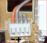
I wonder what is the connection for the LCD backlight.
The connection is 4 pin with LED + and LED - plus others. Please advise how to get back light? can I use the 8V DC
The connection is 4 pin with LED + and LED - plus others. Please advise how to get back light? can I use the 8V DC
ccschua said:I wonder what is the connection for the LCD backlight.
The connection is 4 pin with LED + and LED -
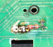
I connected positive just after diodes plus a 5.1kohm series resistor to dim the light (10k was too dim)
Attachments
You could also install a 10K pot just in place of Peters resistor shown above and be able to adjust the light level.
Does anyone know what the normal and peak current draw of the shiga is?
Fran
Does anyone know what the normal and peak current draw of the shiga is?
Fran
woodturner-fran said:You could also install a 10K pot just in place of Peters resistor shown above and be able to adjust the light level.
Does anyone know what the normal and peak current draw of the shiga is?
Fran
I'd have to search for it in one of my previous posts in this thread but I believe the operating current is 210ma on Peters 8v PS circuit.
Regards,
Dan
looking at the picy Peter posted with the resistor on the display board, it looks like the solder bridges the two trace points to the left-upper and lower. Is this intentional?
Another question. What resistors/value has everyone settled on for the series and shunt on the digital output?
Another question. What resistors/value has everyone settled on for the series and shunt on the digital output?
Peter,
I really like your latest version of the Shigy, can you say how difficult it is to machine the acrylic? Also, I'd like to keep everything in 1 case including the transfromer. Bad Idea?
Cheers
Rick
I really like your latest version of the Shigy, can you say how difficult it is to machine the acrylic? Also, I'd like to keep everything in 1 case including the transfromer. Bad Idea?
Cheers
Rick
I did acrylic on a table saw and use router for fine finiszing, no problem here. Be careful when drilling, though; it can sometimes chips.
Transformer can be in a same box, majority of transports is done this way 😉
Transformer can be in a same box, majority of transports is done this way 😉
Badge said:Is this intentional?
Another question. What resistors/value has everyone settled on for the series and shunt on the digital output?
It actually looks like there is a bridge on a LED, but it's not. The other connections can be done in any other way, as long as it works.
I use 300/100R combo on the output (Dale)
- Home
- Source & Line
- Digital Source
- Finally, an affordable CD Transport: the Shigaclone story