What caps are you replacing them with? I don't remove caps marked as "2" anymore.
Sync wires are not needed.
Sync wires are not needed.
Peter Daniel said:What caps are you replacing them with? I don't remove caps marked as "2" anymore.
Sync wires are not needed.
Not quite sure I understand your first question. I'm not replacing them, these are some of the the SMD to be removed as per Okapi's notes page 2. I thought we were advised to follow Okapi's notes and that they were still up to date.
Do you happen to know what the sync wires were for, I'm being curious here? Has it something to do with the on board DAC, guess not huh?
Thanks!
Guy
So you are just removing SMD caps and not electrolytics? Okapi pdf recommends replacing electrolytics as well. My current position is to replace as little as possible, as mentioned here: http://www.diyaudio.com/forums/showthread.php?postid=1669753#post1669753
Sync is probably for synchronized recording to tape cassette, anyway, it should be explained in manual that comes with boombox 😉
Sync is probably for synchronized recording to tape cassette, anyway, it should be explained in manual that comes with boombox 😉
Peter Daniel said:So you are just removing SMD caps and not electrolytics? Okapi pdf recommends replacing electrolytics as well. My current position is to replace as little as possible, as mentioned here: http://www.diyaudio.com/forums/showthread.php?postid=1669753#post1669753
Sync is probably for synchronized recording to tape cassette, anyway, it should be explained in manual that comes with boombox 😉
Sorry, yes removing all the parts mentioned "R" only (SMD and electrolitics) not the "E" yet ...as you suggested me around a month ago. My main concern was the 2 SMD side by side.
For the main PCB, as of today, am I right in saying that you are at least suggesting to remove all what was at first described as "R"?
Thanks.
Guy
Regarding pdf mods, I presently do only "R5", "E5" and removing 3 &4 SMD caps.
"R5" is not needed on the board as that cap is actually replaced by BG STD 1000/25 at the offboard regulator (LM7808 based). E5 is exchanged for BGN 47/50.
That is all I do now.
"R5" is not needed on the board as that cap is actually replaced by BG STD 1000/25 at the offboard regulator (LM7808 based). E5 is exchanged for BGN 47/50.
That is all I do now.
Shigaclone
Peter built one for me about 2 months ago...workmanship is excellent. Great look and finish. Peter is a great guy to do business with, very knowledgable and patient.
Keep the good work
Peter built one for me about 2 months ago...workmanship is excellent. Great look and finish. Peter is a great guy to do business with, very knowledgable and patient.
Keep the good work
Peter Daniel said:Regarding pdf mods, I presently do only "R5", "E5" and removing 3 &4 SMD caps.
"R5" is not needed on the board as that cap is actually replaced by BG STD 1000/25 at the offboard regulator (LM7808 based). E5 is exchanged for BGN 47/50.
That is all I do now.
Cool, good thing I haven't removed 3 & 4 SMD caps. :0)
...and on the board I suspect you also still replace the crystal E7 and remove choke R4, right?
Thanks,
Guy🙂
thanks peter, very helpful with the spdif diagram, I had a feeling it would look like that, but you've certainly given me the courage to attemp this with your thorough explanations and time.
Am liking the 'all in one' prototype, what dac chip have you chosen just out of interest?
stuart
Am liking the 'all in one' prototype, what dac chip have you chosen just out of interest?
stuart
It is my Premium SPDIF DAC with TDA1543 and CS8412:
http://www.diyaudio.com/forums/attachment.php?s=&postid=1170936&stamp=1175179199
http://www.diyaudio.com/forums/attachment.php?s=&postid=1170937&stamp=1175179271
I don't touch the crystal now, but remove the choke.
http://www.diyaudio.com/forums/attachment.php?s=&postid=1170936&stamp=1175179199
http://www.diyaudio.com/forums/attachment.php?s=&postid=1170937&stamp=1175179271
leoparleur said:...and on the board I suspect you also still replace the crystal E7 and remove choke R4, right?
I don't touch the crystal now, but remove the choke.
Re: Shigaclone
Dead on Peter! I've checked in the manual and that's what it says.
I have no doubt, it shows also in his pictures and he is very devoted to this thread. Two thumbs up from me Peter!
Got it! Keep us in touch from what you perceive as different from the original crystal.
Guy🙂
Peter Daniel said:Sync is probably for synchronized recording to tape cassette, anyway, it should be explained in manual that comes with boombox 😉
Dead on Peter! I've checked in the manual and that's what it says.
sebtdi said:Peter built one for me about 2 months ago...workmanship is excellent. Great look and finish. Peter is a great guy to do business with, very knowledgable and patient.
Keep the good work
I have no doubt, it shows also in his pictures and he is very devoted to this thread. Two thumbs up from me Peter!
Peter Daniel said:I don't touch the crystal now, but remove the choke.
Got it! Keep us in touch from what you perceive as different from the original crystal.
Guy🙂
Peter
So it's just remove choke, R5, E5, R3, R4, Add spdif and make an 8 volt PS?
I checked the National semiconductor site, and their application notes suggest TINY values of capacitors around the regulator. Like 0.33uf, and 0.1 uf, not 2200 and 1000uf.
I'm very confused -- why are those values different by 5orders of magnitude?
BigE said:I checked the National semiconductor site, and their application notes suggest TINY values of capacitors around the regulator. Like 0.33uf, and 0.1 uf, not 2200 and 1000uf.
I'm very confused -- why are those values different by 5orders of magnitude?
I wouldn't worry about that, datasheet says: "CI = 0.33μF, CO = 0.1μF, unless otherwise specified." 😉
I agree, those are probably the minimum values for the regulator to meet the specs in the datasheet. It probably also assumes a ripple-free input voltage to start with.
The 100 nF on the output side suppresses the noise created by the regulator itself. I always use a 100 nF cap suitable for HF bypassing (such as a ceramic) as close to the pins of the regulator as possible in addition to the bigger electrolytic.
If you're going to feed the regulator with an unregulated power supply (transformer + rectification + smoothing) then the smoothing cap on the input most certaincly needs to be bigger than the 330 nF mentioned in the datasheet. The mentioned 2200 uF cap should be fine.
Hi all,,
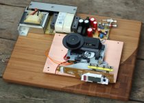
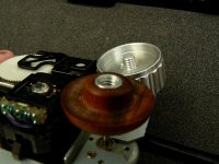
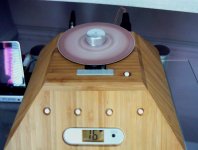
Have just finished trying to make a CD table and Puck, was not easy. The finishing turning was done by fitting the CD table to the cassette motor and spinning it up with a 12v supply.
The puck is a volume knob..
Hope it gives some inspiration..
PS, Thanks to Tripmaster for the link to the threaded inserts..
Attachments
jitter said:The 100 nF on the output side suppresses the noise created by the regulator itself. I always use a 100 nF cap suitable for HF bypassing (such as a ceramic) as close to the pins of the regulator as possible in addition to the bigger electrolytic.
If you're going to feed the regulator with an unregulated power supply (transformer + rectification + smoothing) then the smoothing cap on the input most certaincly needs to be bigger than the 330 nF mentioned in the datasheet. The mentioned 2200 uF cap should be fine.
Excellent, thank you.
It appears that there is no need for a large cap on the output side.
Unless this cap has something to do with defeating the instabilities due to ESR or Inductance, when the supply voltage is close to the output voltage.
But, when using a 2x12 Hammond xformer, the supply voltage is high enough to avoid these issues: it looks like only the noise suppression cap is actually needed. The larger 1000uf cap would not react fast enough to defeat the noise.
FYI: tantalum vs ceramic....looks like ceramic is the clear winner for this application.
http://dataweek.co.za/news.aspx?pklNewsId=27008&pklCategoryID=45
BigE said:It appears that there is no need for a large cap on the output side.
FYI: tantalum vs ceramic....looks like ceramic is the clear winner for this application.
I wouldn't be so sure about that. One time by accident I lost connection on 1000uF cap after regulator (I had it in socket for testing) and I completely lost the bass.
As to tantalum or ceramics, those caps when in parallel with large electrolytic will influence sonics, so do some listening tests before installing them permanently. There is a specific reason why I still remove 3 &4 SMD caps on transport board.
Interesting.... AFAIK, loosing the bass is an indication that the jitter spectrum has changed.
Perhaps the regulator became unstable without any capacitance or noise on the power supply affected the operation of the crystal?
Can the crystal be driven independently from the motor and LCD?
Perhaps the regulator became unstable without any capacitance or noise on the power supply affected the operation of the crystal?
Can the crystal be driven independently from the motor and LCD?
Let's not forget that 8V regulator is only for motors control, there is another 5V regulator on board powering all the chips, including the chip to which oscillator is "attached". In that case, the 8V reg. works only as pre-regulator.
- Home
- Source & Line
- Digital Source
- Finally, an affordable CD Transport: the Shigaclone story