PEQ's for Hole Filler
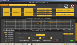
I went in and cleaned up the PEQ's for this setup to just 2 or 3 per driver. As you can see, they are fairly mild and I only used boost on the top end of the tweeter. I think it made the SR more solid. Here are the screenshots of the PEQ curves for the 3 drivers (woofers used channels 1 and 2 which have the same settings).
Low Frequency (Eminence Beta 12cx x qnty 2):
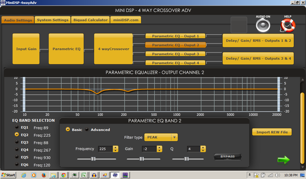
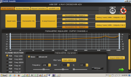
Mid Frequency Filler Driver (Vifa TG9FD10-8 x qnty 2):

High Frequency Tweeter (Dayton DC28F-8):

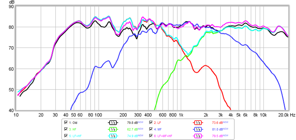
Here is the revised acoustic crossover curve (centered at 1200Hz) showing the old (black) and new (magenta), the hole is shown in cyan:
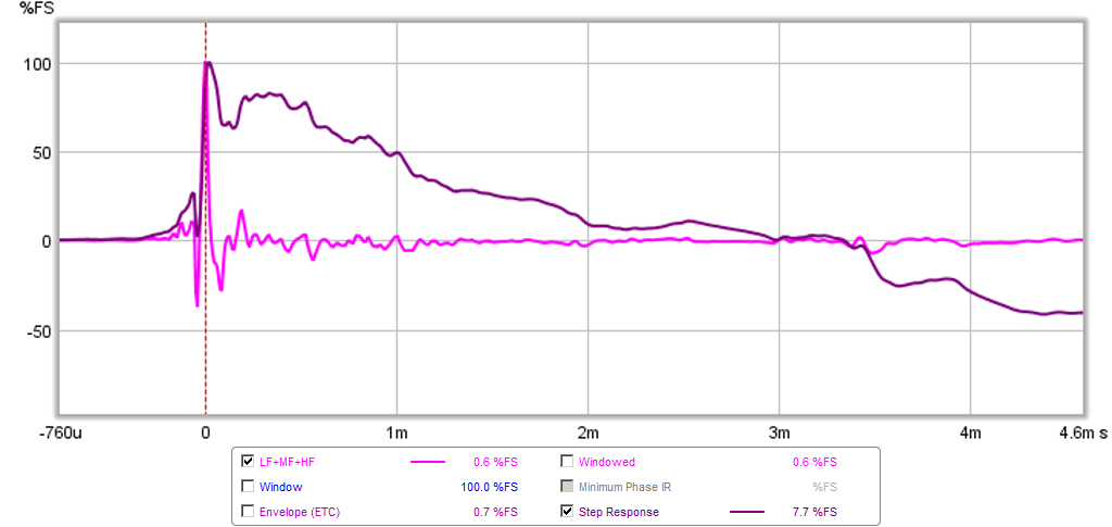
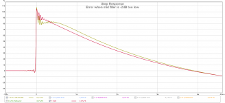
Here is the revised impulse and step response combined:
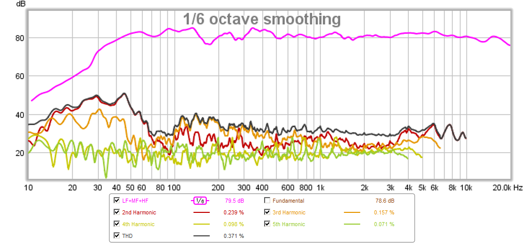
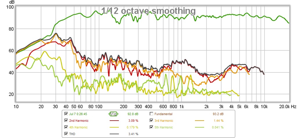
This is the harmonic distortion at 80dB 1m away - farily low level sound:
I haven't had a chance to record square waves yet. Looking at the SR, I am not sure that will do it as there is a dip right after the first tweeter peak.
I went in and cleaned up the PEQ's for this setup to just 2 or 3 per driver. As you can see, they are fairly mild and I only used boost on the top end of the tweeter. I think it made the SR more solid. Here are the screenshots of the PEQ curves for the 3 drivers (woofers used channels 1 and 2 which have the same settings).
Low Frequency (Eminence Beta 12cx x qnty 2):
Mid Frequency Filler Driver (Vifa TG9FD10-8 x qnty 2):
High Frequency Tweeter (Dayton DC28F-8):
Here is the revised acoustic crossover curve (centered at 1200Hz) showing the old (black) and new (magenta), the hole is shown in cyan:
Here is the revised impulse and step response combined:
This is the harmonic distortion at 80dB 1m away - farily low level sound:
I haven't had a chance to record square waves yet. Looking at the SR, I am not sure that will do it as there is a dip right after the first tweeter peak.
Attachments


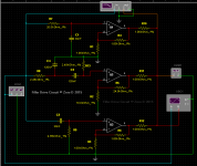
Filler Drive Circuit
Active & Passive
All bands are in phase & 6dB an Octave.
Inspired by the ongoing discussions etc, here's one i designed & simmed. The turnover points could be changed to other frequencies to suit. In this instance for eg, the bass/mid & top xover frequencies are @ 250Hz LP & 1kHz HP @ 6dB an Octave. The Filler bandpass center frequency is 500Hz also @ 6dB an Octave.
Frequency response = + - 0.1dB 1Hz - 20kHz
Phase = + - 1 Degree 1Hz - 20kHz
I realise it's not actually driving real loudspeakers, but each output could feed individual amps which would. Plus i expect that my circuit could be transposed into passive loudspeaker xover/s, connected to actual loudspeakers. Depending on the loudspeakers specs etc, one or more zobel etc networks may need to be included on loudspeaker/s, to tame impedance.
Be interested to know what you think about it, & especially if you sim it, and/or build either the active and/or passive versions. Also if you incorporate it in software. 🙂
Attachments
xrk, your distortion measurement spl level is really low for the purpose (as seen on the chart of REW). Some kind of standard is 90dB/1m, 95dB for large speakers.
Have you tested/calibrated the spl level of REW? Obviously the level that REW shows is not real, because ambient noise level is so low.
Well behaving drivers, nice slopes with such mild peq!
Have you tested/calibrated the spl level of REW? Obviously the level that REW shows is not real, because ambient noise level is so low.
Well behaving drivers, nice slopes with such mild peq!
That is a nice step response XRK971 !
Regarding Sigma Studio: This is a GUI based programming tool for Analog Devices Sigma DSPs.
Many cheap digital crossovers use this processor family. Unfortunately most of the programming tools for these crossovers don't support all the possible functions of the processors. Summing and subtrating are amongst the most convenient ones for crossovers.
John Watkinson once mentioned that a lowpass and a highpass isn't a crossover - it is just a pair of filters.
Even with these constraints one can do a lot - if summing and subtracting is possible as well.
Regards
Charles
Regarding Sigma Studio: This is a GUI based programming tool for Analog Devices Sigma DSPs.
Many cheap digital crossovers use this processor family. Unfortunately most of the programming tools for these crossovers don't support all the possible functions of the processors. Summing and subtrating are amongst the most convenient ones for crossovers.
John Watkinson once mentioned that a lowpass and a highpass isn't a crossover - it is just a pair of filters.
The most complicated thing a base 2x4 or 1x4 miniDSP can do is to have an arbitrary bi-quad polynomial filter. If you can calculate infinite impulse response (IIR) bi quad coefficients you can use them. Each channel can have 6 separate filter. All 4 channels can have 6 common filters. That is 30 filters total. They are all IIR though.
Even with these constraints one can do a lot - if summing and subtracting is possible as well.
Regards
Charles
I realise it's not actually driving real loudspeakers, but each output could feed individual amps which would. Plus i expect that my circuit could be transposed into passive loudspeaker xover/s, connected to actual loudspeakers. Depending on the loudspeakers specs etc, one or more zobel etc networks may need to be included on loudspeaker/s, to tame impedance.
Don't do that !!! Go/stay active !
One more trick: The output signals of the filler driver crossover can also be achieved with the classic three op-amp biquad circuit (attention: the bandpass output is inverted on this one!). One can even go a step further and do the EQing of the natural driver responses by adequate summing of the three output signals.
Regards
Charles
xrk, your distortion measurement spl level is really low for the purpose (as seen on the chart of REW). Some kind of standard is 90dB/1m, 95dB for large speakers.
Have you tested/calibrated the spl level of REW? Obviously the level that REW shows is not real, because ambient noise level is so low.
Well behaving drivers, nice slopes with such mild peq!
I knew someone would ask for this, so I took data at 1m and 90dB. The mic is calibrated so those are real SPL. Ambient is about 46 to 52dB in my basement.
Here is the distortion - about 3.5% THD at 50Hz, as you go higher up, values are quite reasonable. I wonder if the distortion could be all the stuff in the room rattling a higher SPL or maybe the thin 3/8in ply baffle? The is a large welling up at 1kHz and I wonder where that comes from ? Maybe need to do individual drivers to find culprit? It is not bothering me though.
Attachments

Last edited:
I haven't had a chance to record square waves yet. Looking at the SR, I am not sure that will do it as there is a dip right after the first tweeter peak.
At below plots did run some electric loops to force a error dip as yours, it seems if either woofer acoustic center is behind mf/hf section or mid spl in sum is too low the dip turns up. From these visuals a quick guess is delay both mf/hf section 0,09mS more than they are now so woofer get those 0,09mS forward in alignment.
Attachments

Last edited:
Don't do that !!! Go/stay active !
One more trick: The output signals of the filler driver crossover can also be achieved with the classic three op-amp biquad circuit (attention: the bandpass output is inverted on this one!). One can even go a step further and do the EQing of the natural driver responses by adequate summing of the three output signals.
Regards
Charles
Nowadays I know that active quad amping is cheaper than coils and caps. I have priced typical 2 and 4th order xo's and on 2 way it is about the same if you shop for cheapest parts for coils and caps. With 3 channel, there is no way it costs less. My active setup is $150 for 4 channels. If I used op amps I would save about $100 in miniDSP but have cost of pcb for op amps. That would be neat to do with analog op amps. The direct drive probably avoids having to have impedance flattening circuits - and that would double the price of a xo. My guess that ro do this passively is $200 to $300 in passive xo parts for each speaker.
I am thinking of getting a waveguide for my CD and using the PRV 5MR405NDY for the mid for an all around 95dB system.
Why not try the 10F? If I recall correctly you said it was more efficient than the TG?
It's a drop in replacement size wise. For a tweeter I'd look at the XT25SC or the smaller XT19 in a waveguide. Just a thought...
Throw some FIR filtering in the mix and .....
Last edited:
At below plots did run some electric loops to force a error dip as yours, it seems if either woofer acoustic center is behind mf/hf section or mid spl in sum is too low the dip turns up. From these visuals a quick guess is delay both mf/hf section 0,09mS more than they are now so woofer get those 0,09mS forward in alignment.
Byrtt,
Thanks for the detective work. I suspect it is more likely the mid SPL is not high enough. I tried varying the delay 0.02ms at a time and did not manage to fix it.
I have mentioned before that this technique needs a very efficient fullrange. The 5MR450NDY would be perfect. Or maybe two of the more sensitive FF105WK would work?
Why not try the 10F? If I recall correctly you said it was more efficient than the TG?
It's a drop in replacement size wise. For a tweeter I'd look at the XT25SC or the smaller XT19 in a waveguide. Just a thought...
Throw some FIR filtering in the mix and .....
10F's might work but are being used in my ref speakers. I suppose for a test they can come out.
I was just about to buy the XT25 ring radiator. 🙂
The relative ease of implementation with miniDSP has me thinking that maybe a transient perfect "Econowave" 3 way active speaker may be of interest to people. Take standard Econowave topology and add a pro audio mid like 5MR450NDY. Add low cost class D amps. Maybe 100W TDA7498 for bass and TPA3116 for mids and treble. Use 95dB sensitive or more drivers. The 5MR450NDY can handle a lot of power and has exceedingly low distortion. It is a good candidate from standpoint of easily keeping up with 98dB sensitive woofer and CD's via power boosting +4.5dB to be 1.5dB above nominal sensitivity of other two drivers.
Last edited:
You might want to check off axis behavior first, to ensure the goal of the Econowave, smooth power response, can be kept...
If going Econowave route, the XO point of the 5MR450NDY needs to match the waveguide and 12in wide woofer. I suspect a 1.2kHz central freq on mid will have smooth polars up to 2 octaves (4800Hz) from a 5in wide cone before beaming? Let me look at my old polar data in 5MR450NDY thread. The bottom end is 300Hz and that should not be an issue to match the woofer.
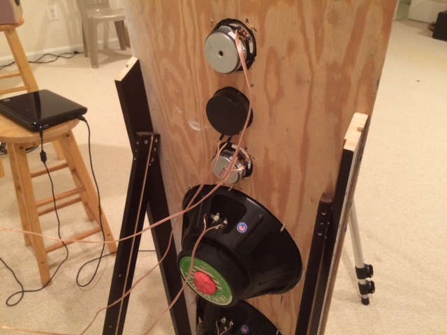
I just want to remind folks out there with woofers, full range drivers, and a tweeter lying around: go cut some holes in a sheet of plywood, hook up your miniDSP and try it! It is loads of fun and quite enjoyable to listen to. I built the speaker in 3 hrs.
Here is a sound clip of some jazz drums and stand up bass playing from a transient perfect OB. There is obviously going to be some ambiance created by the OB back wall reflections so this will sound more diffuse and "live". Very nice rendition and I have not heard such a powerful crescendo of drum hits as this at 31 seconds. The dynamic range of the sound is very nice. Change extension from asc to mp3 to listen.
Attachments
Last edited:
Byrtt,
Thanks for the detective work. I suspect it is more likely the mid SPL is not high enough. I tried varying the delay 0.02ms at a time and did not manage to fix it.
I have mentioned before that this technique needs a very efficient fullrange. The 5MR450NDY would be perfect. Or maybe two of the more sensitive FF105WK would work?
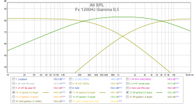
Looking at your steepness of slope the filler has lets say from 300Hz and down to DC, could we suspect this as the culprit for the dip in SR. It was what Barleywater expressed below that made me look at that integration of mid and woofer in present setup. As reference see the soft slope in below picture for mid in a Fx1200Hz gamma 0,5 config and compare to the one you have present. You could do a exercise by try say a 60Hz low shelf boost +3-6dB on mid and see if XO slope for mid gets softer as real BW1 target and improve SR, and if HD plus excursion then still is acceptable. If it turns out this helps then i'm afraid 5MR450NDY can't help in it rolls off to steep down there, FF105WK has better sensitivity but less excursion so think TG9FD is hard to beat.
.....In the end it is step response of each driver that has greatest impact on step response of speaker system. I am in agreement that driver highpass and impedance peak are greatest limitations for step response performance.....
Attachments
phase_accurate
Go/stay active !
Sure active is best, but as others might not be able to, or wish to, the choice is there. Also others are experimenting with passives, so it could help them as well 😉
From what you said, it appears that you think my circuit will work.
The biquad idea sounds like an alternative too.
xrk971
That would be neat to do with analog op amps.
With the addition of another OpAmp used as a buffer on the front of my 3 OpAmp circuit, the total of 4 could be a quad type. Let's say,
Quad OpAmp = $7
Caps/Res = $5
Veroboard/stripboard $5
Case = $15
Power supply = £10
Skts/cable etc = £10
Total = £52 x 2 for stereo = $110 = £60 = Not bad 🙂
The direct drive probably avoids having to have impedance flattening circuits.
It could, yes
Good things to try easily there. Thanks, Byrtt.
Hope it works in that its clear when looking your last plot that mid HP slope has same steepness as HF HP slope, and in that mid slope target is 6dB slope and HF target is 12dB slope there is a chance we can repair that dip and then have chance to see fine as possible SQ-waves : )
Keep an eye on acoustic center calibration settings can need new values when adding such a radical PEQ to mid driver in minimum phase domain (mid get probably slower fire ring), at least its my experience.
Sure active is best, but as others might not be able to, or wish to, the choice is there. Also others are experimenting with passives, so it could help them as well 😉
From what you said, it appears that you think my circuit will work.
The biquad idea sounds like an alternative too.
With the addition of another OpAmp used as a buffer on the front of my 3 OpAmp circuit, the total of 4 could be a quad type. Let's say,
Quad OpAmp = $7
Caps/Res = $5
Veroboard/stripboard $5
Case = $15
Power supply = £10
Skts/cable etc = £10
Total = £52 x 2 for stereo = $110 = £60 = Not bad 🙂
It could, yes
I assumed you designed a LR2-BW1-LR2 active crossover with op amps. I have not looked at it carefully but assuming you did everything right. The key thing to get right are the overlap factors and central frequency. Ability to set individual gains is also nice. The top opamp is for woofer, middle is band pass full range hole filler, and bottom is tweeter right?
I would have to wire it up in TINA (spice from Texas Instruments) to really check. There is a package called FilterPro from TI that lets you design filters like this and it uses standard values of caps and resistors and builds the BOM for you too. Nice package.
In the end, I don't have time to make a proto circuit and design a PCB and solder. $80 for a miniDSP more than covers the labor I would put in to an analog circuit. However, if you want to build one for me and I will hook it up to my system, I am all for that. 🙂
Thank you though.
Edit: just realized you said all bands are BW1? That would have a lot of leakage of woofer breakup into the HF's and also not protect the tweeter from over excursion as much. Is there a reason you went away from LR2 for the woofer and tweeter? Those are the two that need second order slopes. The mid is the most well behaved and 1st order is fine for it.
Last edited:
Maybe soemone would like to have a Bandpass which is 4th order, i.e. having 2nd order slopes. This could be achieved using a 4th order polynomal. This should be feasible in the analog domain and in the digital domain as well. The high and lowpass could even be pulled further apart if necessary.
I anyone is interested I will derive it.
Regards
Charles
I anyone is interested I will derive it.
Regards
Charles
- Status
- Not open for further replies.
- Home
- Loudspeakers
- Multi-Way
- "Filler" driver ala B&O