One example my thoughts for limiting factor is the system high pass and that alone will squeeze some the beatifull SQ-wave shown at that picture.
Couldn't the extra 3dB gain and PEQ for tweeter and woofer be left out if you set 500/2000Hz instead of 580/1720Hz.
I did a little more exploring on location of filter slopes; widening up midrange band pass allows for less gain and less ripple in sum without additional PEQ, but also changes step response as seen when electrical all pass sum is convolved with square waves. Lots of fiddling is to be had in pursuing this approach. The exercise here demonstrates the art and patience for the historically successful implementations; and without good measurements and modeling tools successful setups doubtless consumed copious amounts of time working through iterations of component values and driver choices.
In the end it is step response of each driver that has greatest impact on step response of speaker system. I am in agreement that driver highpass and impedance peak are greatest limitations for step response performance.
Scope, generator and measuring tape are a means of getting delay alignment close, but continuous signal with room reflections can lead to misleading results. I've worked with this in my early efforts and found iterative testing for null with windowed IR measurements and reversed driver polarity more reliable for assessing timing integration of drivers.
I've described timing reference with single microphone without aide of a second loopback channel:
For 2-way design test sweep is loaded into stereo track in one channel, a silence of know length added at end (allowing capture of high frequency decay after sweep finishes), and then at new track end a second copy of sweep is placed in the second channel, followed by adding a finishing block of silence to the end. With known length of sweep and silences, the resulting mono response recording containing separate sweeps for woofer and tweeter is edited into stereo sweeps with perfect time alignment. Each track is convolved with inverse sweep resulting in perfectly aligned IR. Sum of IR predict system response, and the difference of the IR predicts reverse null behavior.
The basic method here allows use of single microphone and periodic signals to get time aligned results, making USB microphones useful. Time aligned measurements in REW with USB microphone requires measuring drivers independently and together, and bumping the solo responses around until observed frequency response and phases for regions outside the crossover overlap region match up. REW allows IR to be shifted by increments as small as 0.1 microsecnds.
Once timing is captured delays are readily simulated in REW and candidate delay applied to appropriate channel.
Overall live iterations of null measurement with REW without loopback is relatively as fast, but requires listening to more sweeps in getting sharp alignment.
PEQ shaping in crossover regions of acoustic response should use fewest number of filters with smallest Q values that achieve good target match; excess Q adds ringing whether the PEQ is boost or cut.
If the intention is to stay with the Mini DSP in the end then it would be easier to use other crossover topologies to achieve a transient perfect crossover.
But maybe you use the filler-driver crossover just for the prototyping of an analog active crossover.
Regards
Charles
But maybe you use the filler-driver crossover just for the prototyping of an analog active crossover.
Regards
Charles
Subtractive-delay (Lipshitz-Vanderkooy) for instance. But I don't know whether the GUI of the Mini DSP does support it.
With sigma-studio for instance it is almost a child's play, apart form the bug that I reported in this thread:
https://ez.analog.com/message/31313
You can see one example if you scroll down a little that was done by subtracting a 2nd order BW lowpass from a pure delay. This ends up in a 3rd order highpass and an overall linear phase.
As always one does of course need to know how to include the driver's natural response.
Regards
Charles
Uhg, crossovers!
>>> ... in which case you're better off IME to follow the pioneers and make the 'filler' a 'FR' driver and shift the XOs outside our most acute hearing BW, i.e. at least the ~500 - 5 kHz BW and ideally the ~250 - 8 kHz BW.
GM
I'm with GM on this.
After reading thru the thread I concur that OB bass is more musical sounding (to me in my rooms) than boxed woofers. I was also surprised how deep OBs played and am hard pressed to consider building anything else other than a 15" woofer on a baffle or in an H-frame for my current apartment. I've got a beautifully built ACI 12" subwoofer looking for a 2 or 3 cubic foot cabinet but it takes up just as much space as an H-frame and I don't recall it sounding as musical - tho it certainly did thump. One day I hope to have the room to build a sub to supplement my OBs.
I have a collection of baffles with various holes cut out for drivers ranging from 3" to 12". It's fun to swap things in and out. It's an addictive hobby! I dedicated one of my closets (the largest one) for keeping the drivers, baffles and various boxes out of the way and easily accesible.
Keep up the good (and interesting) work!
Subtractive filters with IIR based filters yields another set of compromised choices; ready experimentation requires convolution engine, at which point you can get on with linear phase variants of the classics and get down to correcting inherent phase mangling of dynamic drivers.
After reading thru the thread I concur that OB bass is more musical sounding (to me in my rooms) than boxed woofers. I was also surprised how deep OBs played and am hard pressed to consider building anything else other than a 15" woofer on a baffle or in an H-frame for my current apartment. I've got a beautifully built ACI 12" subwoofer looking for a 2 or 3 cubic foot cabinet but it takes up just as much space as an H-frame and I don't recall it sounding as musical - tho it certainly did thump. One day I hope to have the room to build a sub to supplement my OBs.
I think two 12in drivers has the same Sd as a single 15in? Anyhow, I was quite surprised and impressed at the bass you can get. What is different is how much less position dependent it is, I can walk around the room and hear a fairly uniform down to 60Hz bass. If I sit 3 ft in front of it, it digs down to 40Hz. But reduced room modes down to 60Hz was a pleasant surprise. Also, surprising was how well high sensitivity pro audio drivers with lower Qts can work as OB drivers. If using miniDSP it is simple to EQ in a little bass if you want more. So far, for the 90dB SPL's at LP from a single speaker, I am not anywhere near excursion limited on these. They barely move 2mm. It's amazing how good a 3/8in sheet of plywood braced with a couple strips of 1x2 and propped on legs can sound. The legs fold so it can be flattened and put away neatly without too much room required. I am guessing that you can probably do this with fairly inexpensive $30 12in woofers if you XO below 400Hz. A miniDSP and a pair of cheap class D amps, some budget woofers and either the TC9FD or TG9FD can make a nice FAST OB that sounds pretty good.
Subtractive-delay (Lipshitz-Vanderkooy) for instance. But I don't know whether the GUI of the Mini DSP does support it.
With sigma-studio for instance it is almost a child's play, apart form the bug that I reported in this thread:
https://ez.analog.com/message/31313
You can see one example if you scroll down a little that was done by subtracting a 2nd order BW lowpass from a pure delay. This ends up in a 3rd order highpass and an overall linear phase.
As always one does of course need to know how to include the driver's natural response.
Regards
Charles
Is Sigma Studio a wiring diagram based DSP processing software? What hardware do you use? A multi channel sound card?
The most complicated thing a base 2x4 or 1x4 miniDSP can do is to have an arbitrary bi-quad polynomial filter. If you can calculate infinite impulse response (IIR) bi quad coefficients you can use them. Each channel can have 6 separate filter. All 4 channels can have 6 common filters. That is 30 filters total. They are all IIR though.
Last edited:
re:crossovers = good if cost effective and summed right - have to have good drivers in the first place - I don't buy that a FR always sounds more coherent than a multiway. My Frazier CAT40 with cheapish funky horn "in front" of the 8" woofer is pretty good as is Danley's Unity within its range - even the Heresy I other than woofer standing out a bit is decent. Super 10 sounded ragged - a coax with compression driver can be set to sound that way if the highpass is just a cap.
I remember the filler driver B&O sound = good "depth" if on the recording - that was the same era as ESS AMT systems
I remember the filler driver B&O sound = good "depth" if on the recording - that was the same era as ESS AMT systems
The following is in french, but there are a lot of figures which may help you :
it is a part of JM Plantefève's site.
2A & DIY
There are many interesting links in the text.
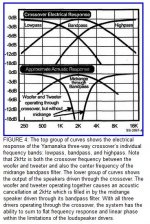
According to an article of AudioXpress, january 2007,
the inventor of the filler configuration was Yamanaka :
A Unique Loudspeaker Crossover Design with Waveform Fidelity
it is a part of JM Plantefève's site.
2A & DIY
There are many interesting links in the text.
According to an article of AudioXpress, january 2007,
the inventor of the filler configuration was Yamanaka :
A Unique Loudspeaker Crossover Design with Waveform Fidelity
@ forr
Thanx for the gammaelectronics link
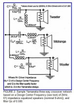
I noticed a relationship between the xover values of FIGURE 2. The values for the filler components are almost a factor of four different. C = X 4 & L = 1/4
Thanx for the gammaelectronics link
I noticed a relationship between the xover values of FIGURE 2. The values for the filler components are almost a factor of four different. C = X 4 & L = 1/4
Success!
I was a bone head... I thought the filler was supposed to be negative phase... 🙂
After reading some more of the writings carefully I saw that the filler mid is supposed to be IN-PHASE with the woofer and tweeter. Looking at its SR, it was upside down and that should have given me a clue.
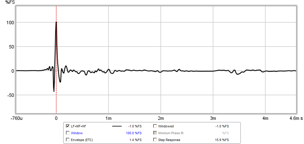
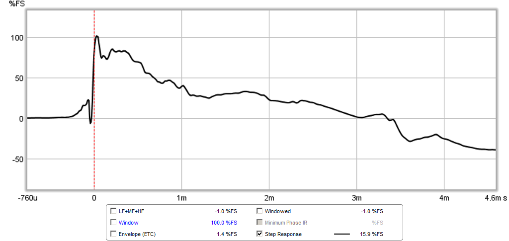
Anyhow, I went back to the non-shaped response, from the first simple LR2-LR2-LR2 xo, and made the mid BW1 and in phase, and what do we get after some very minor delay adjustments? A SR that closely approximates a right triangle. The IR also looks very good. Thus it was not as complicated as I made it out to be. Doesn't seem to require exact textbook acoustic slopes of LR2, BW1, just setting them electrically worked because they are steeper than second and first order once the electrical and natural response were added.
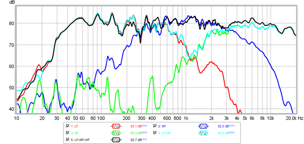
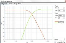
Acoustic XO measured from 1 meter away (ignore LF stuff as HVAC noise was on):
IR:
SR:
Still listening to test tracks now, but so far so good. Very good sound with realistic percussion, piano, guitar, drums, all have that tight time alignment of sharp edge with a smooth follow through.
I was a bone head... I thought the filler was supposed to be negative phase... 🙂
After reading some more of the writings carefully I saw that the filler mid is supposed to be IN-PHASE with the woofer and tweeter. Looking at its SR, it was upside down and that should have given me a clue.
Anyhow, I went back to the non-shaped response, from the first simple LR2-LR2-LR2 xo, and made the mid BW1 and in phase, and what do we get after some very minor delay adjustments? A SR that closely approximates a right triangle. The IR also looks very good. Thus it was not as complicated as I made it out to be. Doesn't seem to require exact textbook acoustic slopes of LR2, BW1, just setting them electrically worked because they are steeper than second and first order once the electrical and natural response were added.
Acoustic XO measured from 1 meter away (ignore LF stuff as HVAC noise was on):
IR:
SR:
Still listening to test tracks now, but so far so good. Very good sound with realistic percussion, piano, guitar, drums, all have that tight time alignment of sharp edge with a smooth follow through.
Attachments


Last edited:
Nice! BYRTT tried to tell you 😉:
Doesn't matter, these things happen right? With all the speakers on your plate it isn't that difficult to overlook something like that.
Looks very good so far... that's a good start I'd say. The theory works well.
Sorry get confused the flip phase talk and where we are, but can we agree LF/MF/HF sections shall be wired in same normal polarity and therefor if one runs LR2 at 1200Hz for LF and HF section and we disconnect MF we get a normal 2 way system but with a deep suchout because phase 180º apart and should be, points for MF then be 600Hz BW1 HP and 2400Hz BW1 LP filters to form band pass.
Doesn't matter, these things happen right? With all the speakers on your plate it isn't that difficult to overlook something like that.
Looks very good so far... that's a good start I'd say. The theory works well.
That's why I said I was a bone head. Byrtt is really good at catching these things.
I had to cut gain on woofers by -4dB ea or -7dB total and this means I need a more efficient mid and tweeter to keep up with the woofers. Or I could just make this a single woofer system, but then it's nice to have low distortion bass. I guess I could wire them in series for even lower distortion?
I am thinking of getting a waveguide for my CD and using the PRV 5MR405NDY for the mid for an all around 95dB system.
xrk971,
Great you got success, but you forgot about take a break : )
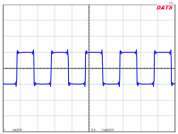
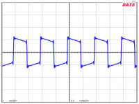
Now as we discovered DATS software have that nice signal generator and Oscilloscope (set scope to single channel up in left corner), will you at some time share OB setup SQ waves. Below is some data other SQ wave to live up to.
Picture below is DATS software 500Hz SQ-wave performance run thru XO filter with LR2 center at 1200Hz and BW1 filler at 600/2400Hz bandpass, without real drivers but pure electric summing, first is without a system bandpass set and second have system bandpass set at 40/22.000Hz BW2 slopes.
In post 70 member forr (thanks links) pointed to a nice French site and at that found this link to SQ wave performance for a B&O speaker back in 1976.
Link: https://docs.google.com/open?id=0BwTS40IaQa16ckdKOVEtQ2xSOUNoR2JhOGV4TVFjdw.
Great you got success, but you forgot about take a break : )
Now as we discovered DATS software have that nice signal generator and Oscilloscope (set scope to single channel up in left corner), will you at some time share OB setup SQ waves. Below is some data other SQ wave to live up to.
Picture below is DATS software 500Hz SQ-wave performance run thru XO filter with LR2 center at 1200Hz and BW1 filler at 600/2400Hz bandpass, without real drivers but pure electric summing, first is without a system bandpass set and second have system bandpass set at 40/22.000Hz BW2 slopes.
In post 70 member forr (thanks links) pointed to a nice French site and at that found this link to SQ wave performance for a B&O speaker back in 1976.
Link: https://docs.google.com/open?id=0BwTS40IaQa16ckdKOVEtQ2xSOUNoR2JhOGV4TVFjdw.
Attachments
Last edited:
Looks nice; would you be willing to show some square wave results or post IR.wav?
This certainly appears to be sterling example of miniDSP/active crossover is capable of.
How many bands of PEQ did you end up using?
Edit: I see BYRTT beat me to the square wave request; seems we are like minded on this.
This certainly appears to be sterling example of miniDSP/active crossover is capable of.
How many bands of PEQ did you end up using?
Edit: I see BYRTT beat me to the square wave request; seems we are like minded on this.
Last edited:
We haven't had a thread this interesting in ages! 🙂
I'm gripped.
I've been looking at some target responses. They are full of surprises and even the occasional +3dB bump in frequency response.
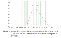
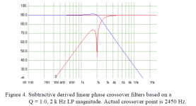
Here's some 2 and 3 way stuff by John Kreskovsky and Yamanaka and B&O.
A lot of this stuff seems to work with time aligned series filters very well. Especially Bud Fried's style. Which is a bit off-topic but something I play with a lot. Put a +3db bump time aligned design on a flat baffle and it turns into a flatter butterworth.
So this is just to enjoy really. John's subtractive filter with the deep tweeter notch is most surprising. Who'd have thought of trying that? 😀
I'm gripped.
I've been looking at some target responses. They are full of surprises and even the occasional +3dB bump in frequency response.
Here's some 2 and 3 way stuff by John Kreskovsky and Yamanaka and B&O.
A lot of this stuff seems to work with time aligned series filters very well. Especially Bud Fried's style. Which is a bit off-topic but something I play with a lot. Put a +3db bump time aligned design on a flat baffle and it turns into a flatter butterworth.
So this is just to enjoy really. John's subtractive filter with the deep tweeter notch is most surprising. Who'd have thought of trying that? 😀
Attachments

Yup. I read it. Impedance equalisation matters. What's your point? 🙂
- Status
- Not open for further replies.
- Home
- Loudspeakers
- Multi-Way
- "Filler" driver ala B&O