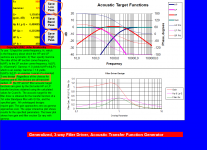
John K's spreadsheet shows different overlap factors that allow a wider "hole" whereas the patent shows the LF and HF driver having a crossover at the same frequency such that a deep hole or null is created. Will the wider hole (less overlap between LF and HF) still yield a transient perfect response?
Seems a big YES, see text marked by orange colour in below picture.
Also marked by orange is the three bottoms to remind one can export curves as frd files and overlay them in REW measurements and have the actual visual target to hit when tweaking miniDSP or whatever tech used to tune for right slopes.
Thanks again sharing xrk971 it's very interesting stuff, your exercise would probably benefit us all to get better knowledge/speakers/possibilities.
Attachments
Last edited:
.....I'm not really sure what I am looking for in a sim either, since mine doesn't output impulse response! 😕
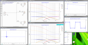
Software in link is free and can output impulse response even step response and square wave plots is a feature http://www.diyaudio.com/forums/multi-way/259865-xsim-free-crossover-designer.html.
Example from XSim in below picture show a filler setup around 2kHz point, frq plot two show the such out when filler is pulled out of circuit, the drivers used are perfect bandwidth ones from DC-infinite to show the perfect sum of filters and always 90º apart, in real world SR/IR/square waves would degrade some when real frd and zma files are linked the three drivers with their real passband data : (
.....This reminds me of two way third order butterworth. The polarity that gets the tweeter phase above the bass is theoretically better on transients than the opposite. I can never hear it though. In fact I prefer the sound of the worse one. 😕.....
Mayby i misunderstand some in above, and if you mean change polarity with even order filters forget next line : )
Think if polarity is turned with odd order filter and the tilted vertical lobing this gives, then changing polarity the new tilt is same as physical change position of tweeter and midwoofer (turning speaker box 180º upside down) and this could cheat that one prefer the less theoretically better on transients.
Nor could I ever hear an allpass network in circuit with speakers or headphones when I did this 30 years ago. But maybe I didn't know what to listen for.
Months back had half an hour exercise with free RePhase, now in 2 minutes i can produce a FIR anti-phase impulse response file that when used as plugin in JRiver or Foobar for a 2 way speaker brings back step response and square waves for that acoustic XO point and slope. If you can find the time it's worth know the difference, for my system at first its a not knight and day mod and some tracks seems to not react much but after more than 10 minutes of listening one can get caught.
It can be hard to express a audio listening experience from person to person with words in the same way, but i can agree with the Duelund XO paper page 9 when i neutralize phase turn on a 2 way speaker with LR4 XO. Duelund says at that page QUOTE The Q-value is 0.707 and will give ringing in the step response. This is heard as a focusing on the instrument(s), minimising the recorded sound from the surroundings. UNQUOTE.
Attachments
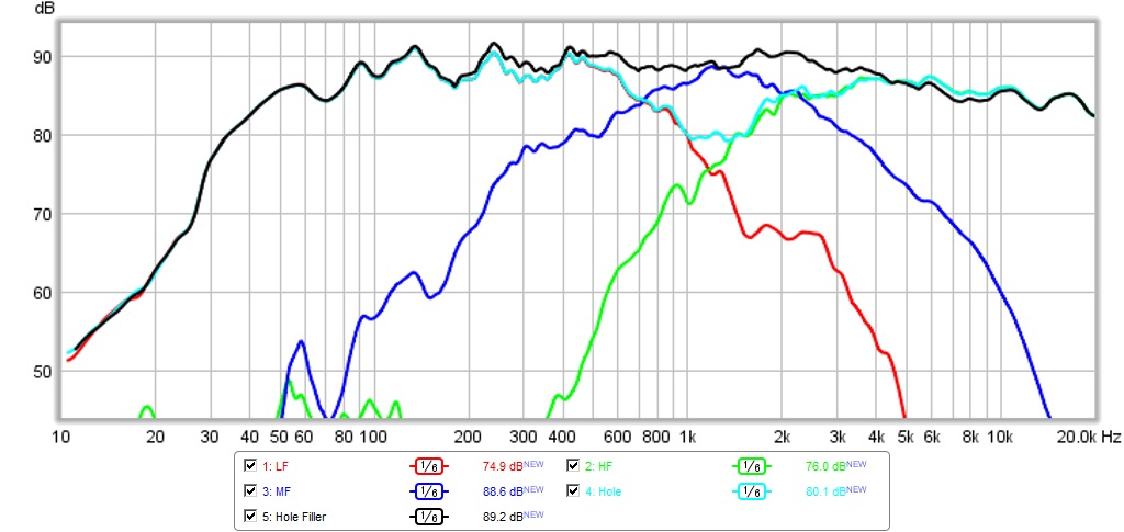
I had some time to fiddle with this test bed speaker today. Trying to get the LR2-BW1-LR2 transient perfect thing going. Settled on 1200Hz as central frequency. Making some progress and here is acoustical crossover measured so far. I am not use to a large speaker like this but the dynamic range and clarity is quite stunning. It's been a real pleasure to listen to - even though it's just a "test bed" for learning.
I think I will have to finally resort to overlaying the ideal response in REW calculated from the spreadsheet and then tweak each response to match via PEQ.
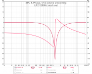
Here is measured acoustical xo. Note the magenta color shows the "hole" that gets filled by the mid.
I think I will have to finally resort to overlaying the ideal response in REW calculated from the spreadsheet and then tweak each response to match via PEQ.
Here is measured acoustical xo. Note the magenta color shows the "hole" that gets filled by the mid.
Attachments
Last edited:
Months back had half an hour exercise with free RePhase, now in 2 minutes i can produce a FIR anti-phase impulse response file that when used as plugin in JRiver or Foobar for a 2 way speaker brings back step response and square waves for that acoustic XO point and slope. If you can find the time it's worth know the difference, for my system at first its a not knight and day mod and some tracks seems to not react much but after more than 10 minutes of listening one can get caught.
It can be hard to express a audio listening experience from person to person with words in the same way, but i can agree with the Duelund XO paper page 9 when i neutralize phase turn on a 2 way speaker with LR4 XO. Duelund says at that page QUOTE The Q-value is 0.707 and will give ringing in the step response. This is heard as a focusing on the instrument(s), minimising the recorded sound from the surroundings. UNQUOTE.
Exactly! 🙂
Thanks plot X look forward down road see some SR : )
Sounds good idea to make target curves to use as overlays, also pull mid and check for deepest suck out could help i think, as little help i made the LR2 1200Hz such out seen in below picture as a frd file in zip folder this could be used as target curve into REW too for quality check. Frd file is set at 0dB so just shift offset to speakers sensitivity area.
I haven't had time to look at the many helpfull hints Barleywater had posted at various threads, but i suspect he has knowledge to do this much easyer that manual tweaking to hit a target curve. Something ala use his hints to use kirkeby reverse tools to smooth measured driver response then subtract target frd file from spreadsheet and in the end output that to a biquad for miniDSP. If anybody can help automate this it would be much faster/easy for xrk971 try out various XO points and gamma values from spreadsheet by John Kreshovsky, and probably later the Duelund filters.
Have been too lazy looking at spacing and wavelength for your build but i did remember a thread touching same subject have a lot of concern about those points http://www.diyaudio.com/forums/multi-way/174276-wmtmw-baekgaard.html.
Attachments
Not much I could have done with spacing except maybe another inch closer between the woofers. I needed some wood there in between to keep baffle strong though. All drivers are as close an they are going to get. Or are you saying I should have had one of the woofers on top for symmetric WMTMW? I could have cut the bezel of the tweeter down and saved another half inch between each mid.
xrk971,
Regarding driver placement and spacing worried the performance will only exist at the measured 0,5 meter point in space on axis of tweeter and at farther distances and other locations there will be too big acoustic errors compared to what the pure perfect electric principle can perform, and then lead to a conclusion how it subjective sounds out in room are based on wrong premise. In principle if gamma set to B&O standard 0,5 the deep such out with filler pulled out of circuit should be more than 30dB and any deviation lead to errors, to get near or best at this think spacing and finding real acoustic offset tweaking value at choosen XO point needs much care to get precise.
Guess symmetry with second woofer on top would have been better and smaller diameter could have helped too, but you could cheat little on woofer distance by disconnect the bottom one because wouldn't that move present woofer center from to be right between the two woofers to center of the top woofer.
Last edited:
Make it a 3.5 way with a simple passive crossover between the woofers?
My take would be to optimize it for the chosen listening distance. After that test a couple of distances to research the effect of that.
My take would be to optimize it for the chosen listening distance. After that test a couple of distances to research the effect of that.
I have 4 independent channels so can make it a 4 way with bottom woofer from 100Hz and below so spacing not important. Or I can optimize xo at listening position. I measured at LP yesterday and response was still flat but had a downward tilt at HF. The 0.5m measurement was good from response standpoint - although phase will be hard to determine when it is that far out with reflections. Or I can leave bottom woofer same as upper woofer but adjust time delay to allow for longer transit time to LP. Imagine it is one those Huge 7 speaker Dunlavy's without the top complement of woofers.
wesayso,
Good points even phase precision is hard to track for mutiway system in real room at long distance as X points out, is FR IR and SR figure then enough to reveal how close one are.
xrk971,
Since you haven't shown SR yet are they bad : )
Good points even phase precision is hard to track for mutiway system in real room at long distance as X points out, is FR IR and SR figure then enough to reveal how close one are.
xrk971,
Since you haven't shown SR yet are they bad : )
wesayso,
Good points even phase precision is hard to track for mutiway system in real room at long distance as X points out, is FR IR and SR figure then enough to reveal how close one are.
xrk971,
Since you haven't shown SR yet are they bad : )
It's not what I want yet, but here is open disclosure so you can see progress. I just created FRD files in John K's spreadsheet for 1200Hz and 0.6 overlap factor. Will try to massage the drivers into this response - can be tough going but will be worth it when they all sum up nicely. As compromise will do measurements at 1m, (half dist for LP).
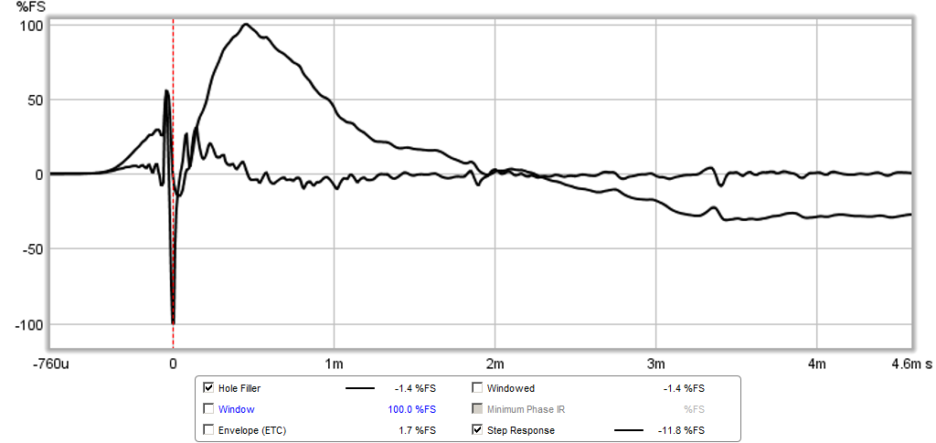
Here is current IR/SR that goes with previous xo plot (I have a LONG way to go):
Attachments

Thanks SR plot as you say long way to go, but it's hard to track reallity when all traces are black, i'm green in this but do some guessing shouldn't IR/SR both go positive and then get woofer about 0,4-0,5mS forward in time domain by delay the others.
Not shure we agree or is usefull but take from below what you find valueable put time into, it's two things i would do before tuning for target curves.
From previous personal experience which cheated me : ) i would check with 1,5V batteri if cone move forward when positive is connected to drivers red terminal for all drivers as supposed to and recheck that the three sections are all wired normal polarity to amps. Lastly if amps are a different type check datasheet that they output either normal or inverted polarity for all of them and correct if any amp throw reverse.
Based drivers raw response would then put some time in finding acoustic center at common point in space on axis of tweeter but for all three sections at XO point and load their corrections into miniDSP. Know it can change little when later they EQed but think this is better start that nothing. With a USB microphone this point often take me a lot of invested time and therefor intend in future to put my old un-calibrated analog Behringer into service for this task by setting check mark for the function "Use Loopback as Timing Reference" in REW settings.
Last edited:
X,
Your exuberance and stamina are A1! I get run down just trying to follow you.
I downloaded XSim and set up BYRTT's sim, then loaded component values into LTSpice and generated wave output with swept sine wave input. From this IR.wav was generated; this is for intents and purposes here is a transient perfect response. BYRTT's comments about real drivers hold as limiting factor for results.
For your LR2-BW1-LR2 approach I simulated in Cool Edit; Woofer LR2 generated as cascaded 580Hz BW1 low pass, tweeter LR2 generated as cascaded 1720Hz BW1 high pass, and midrange generated as 1kHz BW1 low pass cascaded with 1kHz BW1 high pass. 9dB gain applied to midrange makes for good sum with woofer and tweeter filters. A somewhat more appealing result was obtained with midrange gain of 12dB summed with woofer and tweeter followed by application of PEQ 1kHz, -5.2dB with Q=.707.
Last edited:
Thanks for the kind words Barleywater.
I just spent 2 hrs manipulating the responses to match the target curves. It takes way too much PEQ to do so, and I fear this is putting all sorts of phase anomalies on the signal. The summed result seemed to be to high at the XO frequency. Bulged up. Don't know what is happening but it doesn't sound great. Anyhow, back to the drawing board. The last setup I had sounded much better. Will need to think and perhaps do some xsim or PCD modeling before doing it empirically again. Very time consuming.
This B&O hole filler XO is harder to implement than it looks. With miniDSP you would think it is easy. Can't imagine doing this with passives. One thing I see now is that if you need a lot of mid range sensitivity to do this. Maybe a PRV 5MR450NDY with 95dB sensitivity and 250Hz to 15kHz bandwidth would have been a better choice?
Will have to take a break from this for a few days I think.
Last edited:
Barleywater,
Always learn a lot from your guides and hints thanks posting.
Agree, that said can't thank X enough for sharing helping and educate us all to better speakers and ideas 🙂.
One example my thoughts for limiting factor is the system high pass and that alone will squeeze some the beatifull SQ-wave shown at that picture.
Couldn't the extra 3dB gain and PEQ for tweeter and woofer be left out if you set 500/2000Hz instead of 580/1720Hz. Say this because some time back via soundcard loopback and JRiver virtual sound device as output in REW i got that setup to confirm the sum is real in electric loop. Unfortunately haven't saved the plots but if remember correct when i sat limiting passband on the three drivers instead of infinite bandwidth small things was happening and would need some correction but i stopped putting more time into it at that point.
Always learn a lot from your guides and hints thanks posting.
X,
Your exuberance and stamina are A1! I get run down just trying to follow you.
Agree, that said can't thank X enough for sharing helping and educate us all to better speakers and ideas 🙂.
.....I downloaded XSim and set up BYRTT's sim, then loaded component values into LTSpice and generated wave output with swept sine wave input. From this IR.wav was generated; this is for intents and purposes here is a transient perfect response. BYRTT's comments about real drivers hold as limiting factor for results. .....
One example my thoughts for limiting factor is the system high pass and that alone will squeeze some the beatifull SQ-wave shown at that picture.
.....For your LR2-BW1-LR2 approach I simulated in Cool Edit; Woofer LR2 generated as cascaded 580Hz BW1 low pass, tweeter LR2 generated as cascaded 1720Hz BW1 high pass, and midrange generated as 1kHz BW1 low pass cascaded with 1kHz BW1 high pass. 9dB gain applied to midrange makes for good sum with woofer and tweeter filters. A somewhat more appealing result was obtained with midrange gain of 12dB summed with woofer and tweeter followed by application of PEQ 1kHz, -5.2dB with Q=.707.
Couldn't the extra 3dB gain and PEQ for tweeter and woofer be left out if you set 500/2000Hz instead of 580/1720Hz. Say this because some time back via soundcard loopback and JRiver virtual sound device as output in REW i got that setup to confirm the sum is real in electric loop. Unfortunately haven't saved the plots but if remember correct when i sat limiting passband on the three drivers instead of infinite bandwidth small things was happening and would need some correction but i stopped putting more time into it at that point.
Last edited:
Thanks SR plot as you say long way to go, but it's hard to track reallity when all traces are black, i'm green in this but do some guessing shouldn't IR/SR both go positive and then get woofer about 0,4-0,5mS forward in time domain by delay the others.
Not shure we agree or is usefull but take from below what you find valueable put time into, it's two things i would do before tuning for target curves.
From previous personal experience which cheated me : ) i would check with 1,5V batteri if cone move forward when positive is connected to drivers red terminal for all drivers as supposed to and recheck that the three sections are all wired normal polarity to amps. Lastly if amps are a different type check datasheet that they output either normal or inverted polarity for all of them and correct if any amp throw reverse.
Based drivers raw response would then put some time in finding acoustic center at common point in space on axis of tweeter but for all three sections at XO point and load their corrections into miniDSP. Know it can change little when later they EQed but think this is better start that nothing. With a USB microphone this point often take me a lot of invested time and therefor intend in future to put my old un-calibrated analog Behringer into service for this task by setting check mark for the function "Use Loopback as Timing Reference" in REW settings.
The downward spike has some thing to do with EQ. The polarity of the amps and driver has been checked and it pushes out on kick drum. Soft dome is assumed to be correct because a hole appears due to woofer and tweeter phase flip when both set at same polarity.
What is the process for getting rough time alignment settings? Measure where voice coil is located relative to baffle?
Agree could be good idea take a break some days away from this time consuming setup : )
Sorry get confused the flip phase talk and where we are, but can we agree LF/MF/HF sections shall be wired in same normal polarity and therefor if one runs LR2 at 1200Hz for LF and HF section and we disconnect MF we get a normal 2 way system but with a deep suchout because phase 180º apart and should be, points for MF then be 600Hz BW1 HP and 2400Hz BW1 LP filters to form band pass.
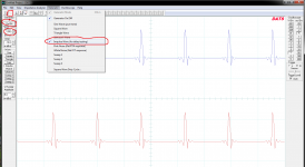
Have a clumsy time consuming procedure to find acoustic center drivers between at a certain frq which lean on SR for a BW1 filter. In mean time have discovered but not tried yet our good DATS 2.0 software has a promising looking feature for this. Setting it up first to do is in "Audio Device Selection" meny change sound device I/O to soundcard and USB microphone there after see below picture where to set generator for XO point which this time is 1200Hz and start the generator and Oscilloscope.
One then gets the shown impulses train which can be zoomed in out at right with V/Div and ms/Div keys. My guess is then with mic on axis tweeter one can manual physical by hand connect one driver at a time and see how impulse point at plot change in time and by this tweak miniDSP delay for drivers until they hit same spot. Also connecting them all at a time impulse should stay same point and maybe one can have example tweeter send impulse then connect mid with flipped polarity shouldn't they then cansel. Hmm.. it looks very convenient tool look forward if you try it live and it can do the job.
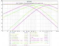
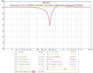
Also did set up my JRiver DSP to run real electric loopback with REW listening loop. There discovered (see picture two) the gamma setting 0,5 is not the simple LR2 center with BW1 bandpass at one octave below and one octave above LR2 center frq, to hit that one gamma should be set at 1,0.
Can understand your frustration when tweaking for target, at picture three see the perfect sum (orange) from LR2 set 1200Hz for LF/HF and BW1 at 600/2400Hz bandpass. The red plot then show LF set back error of 0,36mS and what a FR error this gives. Acoustic center seems need to be set right here before any good target curves summing will show up as predicted.
Attachments
Thanks for the tip on using the Oscope in DATS to find time alignment. I also used to set tone generator at XO freq and adjust delay to get deepest null in flipped polarity.
- Status
- Not open for further replies.
- Home
- Loudspeakers
- Multi-Way
- "Filler" driver ala B&O