Yup. I have a Siglent SPD3303X-E which I purchased for just $100 as it was used. The product was mint though and extremely useful for all my lab experiments. It only goes to +/- 32V but that's okay for initial testing.
https://siglentna.com/power-supplies/spd3303x-spd3303x-e-series-programmable-dc-power-supply/
I also have a Hewlett Packard 6237B (for low voltage testing) which was lovingly cared for by Tom Christiansen and sold to me. Built like a tank:
https://www.ebay.com/itm/225360761177?hash=item34788c5159:g:WvQAAOSwh8Zjx-Mr
The HP 6237B is what I used to test the panel mount BTSB.
As far as consistency, quality and reliability, the HP is right up there with the best albeit a bit expensive.
Best,
Anand.
Last edited:

Everyone, you are all saints! I owe you all beers, coffee, tea, whatever. I have a bench supply in my amazon list but it's not as nice as the one X linked, so I'll be grabbing one of those.
Many apologies for the delay, just when you think you can avoid work, work becomes busy.
X you were spot on. I turned the bias pots fully clockwise, and now I am at 0mV and pass the dim bulb test. I still need to wire up the power for the 2nd amp board, as well as the SSR protection boards, input and speakers, then I can adjust bias and get to listening.
Thank you so much everyone! Still a bit busy at work but I will update later with further progress.
Sorry for the false alarm, my biggest lesson learned here is, don't go trying to be clever and just leave the pot alone on first turn on. For my curiosity, I've never run into this or ever maxed a bias pot on an amp, had I not had a dim bulb tester, what would have happened? Smoke or just very hot heatsinks?
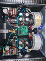
Proof in the pudding with some pictures showing LEDs are on. Vunce you can see my LED's connected to the low capacitance PSU's in the front, I tapped 1.5mm holes through the front plate, and then widened the inside of the hole to 3mm a tiny bit to give the LED a bit of something to bite into before I silicone it on (or is there a better way?). I did the low cap boards as I figured they are almost end of the line LEDs and if they aren't on surely I won't be producing sound.
Many apologies for the delay, just when you think you can avoid work, work becomes busy.
X you were spot on. I turned the bias pots fully clockwise, and now I am at 0mV and pass the dim bulb test. I still need to wire up the power for the 2nd amp board, as well as the SSR protection boards, input and speakers, then I can adjust bias and get to listening.
Thank you so much everyone! Still a bit busy at work but I will update later with further progress.
Sorry for the false alarm, my biggest lesson learned here is, don't go trying to be clever and just leave the pot alone on first turn on. For my curiosity, I've never run into this or ever maxed a bias pot on an amp, had I not had a dim bulb tester, what would have happened? Smoke or just very hot heatsinks?
Proof in the pudding with some pictures showing LEDs are on. Vunce you can see my LED's connected to the low capacitance PSU's in the front, I tapped 1.5mm holes through the front plate, and then widened the inside of the hole to 3mm a tiny bit to give the LED a bit of something to bite into before I silicone it on (or is there a better way?). I did the low cap boards as I figured they are almost end of the line LEDs and if they aren't on surely I won't be producing sound.
Attachments

Fantastic BH! Your very close to hearing music. Nice idea bringing the LED's to the front panel, you'll immediately see when the protection boards cut out at powering off.
You've got plenty of heatsink for this amp, twist the bias up! 😆
You've got plenty of heatsink for this amp, twist the bias up! 😆
Great news Bloqhead. You are very close to having music play. Set the bias current between 80mA and 120mA. So about 26mV across the test points on the 0.22R source resistors. Good idea to see the LED status of the SSR.
That is a sweet looking dual mono setup. They way you have your star ground for chassis running to all the protective earth grounds indicates this will be very quiet hum free amp.
Good luck with the rest of the testing.
That is a sweet looking dual mono setup. They way you have your star ground for chassis running to all the protective earth grounds indicates this will be very quiet hum free amp.
Good luck with the rest of the testing.
Glad it's sorted. When I assembled/tested I left the pot as they came from factory, must have been half way, and only required a little adjustment...
I also used the SSR PSU board as power indicator, but I put a header where the led is and then ran that to the power led under the power button on mine. Same thing, no led no sound... Works great.
Nik.
I also used the SSR PSU board as power indicator, but I put a header where the led is and then ran that to the power led under the power button on mine. Same thing, no led no sound... Works great.
Nik.
You're all fantastic, can't express my thanks enough.
Both amp boards have power now, passed the dim bulb test, and nothing exploded when I went straight to the outlet 😀
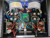
Question in regards to being hum free and the most ideal path for speaker returns, Each different color line on the below picture represents a different potential path for speaker return, which is the most ideal?
Dark blue = binding post -> amp board.
Light blue = binding post -> SSR protection -> amp board
Yellow = binding post -> common on PSU

Both amp boards have power now, passed the dim bulb test, and nothing exploded when I went straight to the outlet 😀
Question in regards to being hum free and the most ideal path for speaker returns, Each different color line on the below picture represents a different potential path for speaker return, which is the most ideal?
Dark blue = binding post -> amp board.
Light blue = binding post -> SSR protection -> amp board
Yellow = binding post -> common on PSU
I have done it both ways but technically, having speaker return go straight to PSU ground node (yellow path) is best as it goes back directly to the source. Here is what I did for Alpha Nirvana, albeit it was not a dual mono block.

The way I wired my Griddle Amp was much closer to what you have in the dark blue path. That amp is dead quiet.
In the end, it sometimes depends on your exact setup so try various ways and listen. Press your ear to the speaker. Or use a headphone to trace the sound. Fluke DMM in mV rms mode is also handy.
Sometimes rotating the toroidal trafo axis helps too. How wires cross each other or are running parallel to audio input affects noise too. Sometimes a more random rats nest is quieter than neat 90deg bends all zip tied together. 🙂
I'll match that then, if it's no good I will try direct to the PSU board, thanks!
Good news, I now have the amp turned on, dialed in the pots to ~33mV, so ~150mA per the schematic on post #1 for a smoother ride, I believe I saw throughout the thread that others have settled at that point as well. Still need to whip up some short input cables but that won't take long, need to decide between easier to work with Mogami W2330 or some Gotham GAC-1, I guess for a 4inch run who cares? Music will hopefully play tonight yet.
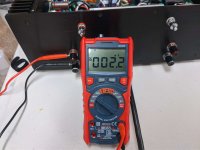
I don't have a fluke, but I do have a bunch of at least decent DMM's, here's a pic. It has only been about 10 minutes, heatsinks aren't even warm. I'll keep checking back every little bit while I tidy up my mess and keep the bias at 33mV. When I am finally ready to button it up I'll mount the LEDs once and for all. If anyone's curious, my TP Link outlet says the amp is idling at 45watts, 120vac mains.

Good news, I now have the amp turned on, dialed in the pots to ~33mV, so ~150mA per the schematic on post #1 for a smoother ride, I believe I saw throughout the thread that others have settled at that point as well. Still need to whip up some short input cables but that won't take long, need to decide between easier to work with Mogami W2330 or some Gotham GAC-1, I guess for a 4inch run who cares? Music will hopefully play tonight yet.
I don't have a fluke, but I do have a bunch of at least decent DMM's, here's a pic. It has only been about 10 minutes, heatsinks aren't even warm. I'll keep checking back every little bit while I tidy up my mess and keep the bias at 33mV. When I am finally ready to button it up I'll mount the LEDs once and for all. If anyone's curious, my TP Link outlet says the amp is idling at 45watts, 120vac mains.
Another FH9HVX has been born! Assuming that DC offset is measured by putting the DMM leads to the pos and neg output of the amp, at the binding posts I get anywhere from 1.2-2.2mV with inputs shorted. Letting it sit for several hours it seems to want to settle in between 33-36mV on the 0.22R source resistors. Considering the size of my heatsinks and the fact that after 2-3 hours of idle they were barely 82F in a 70F ambient room, I think I will leave it as is unless instructed otherwise. With a 4.7uF 63VDC cap on the low capacitance PSU's, I think the boards drain faster than the spring on my power switch can release.
Off to listening! Enjoy some pics, I'll come back with my insights on the sound. Cheers and have a good weekend everyone!
Off to listening! Enjoy some pics, I'll come back with my insights on the sound. Cheers and have a good weekend everyone!
Attachments
Last edited:
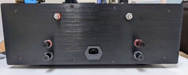
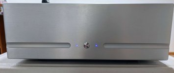
Very nice build Bloqhead! I like what you did with the two small LED holes for the SSR power indicator. Looks like the same Viborg binding posts I like to use. So the front panel button switch is switching the full AC mains?
Looks like you could use the SFP Plus (SFPP) board with remote low voltage power on/standby switching in future projects. I’ll try to make that available soon. It also has the logic control for the speaker protect SSR to turn them on with a slight delay to avoid thump and turn off instantly when the mains AC SSR is disabled.

Looking forward to you listening impressions. Your chassis looks beautiful. You could turn the bias current up even higher since your heatsink is so massive (if you wanted). This would extend the first couple of watts higher into Class A operation. Not a big deal though.
Looks like you could use the SFP Plus (SFPP) board with remote low voltage power on/standby switching in future projects. I’ll try to make that available soon. It also has the logic control for the speaker protect SSR to turn them on with a slight delay to avoid thump and turn off instantly when the mains AC SSR is disabled.
Looking forward to you listening impressions. Your chassis looks beautiful. You could turn the bias current up even higher since your heatsink is so massive (if you wanted). This would extend the first couple of watts higher into Class A operation. Not a big deal though.
Very nice build BH! Very polished and professional looking. I like the power indicator LED's. May try something similar when I get to that point. Congrats!
Super build BH! Love that beefy chassis 😉
I definitely preferred the sound with higher bias current, mine is in the neighborhood of 150-160mA just as yours.
Time to kick back and enjoy the fruits of your labor!

I definitely preferred the sound with higher bias current, mine is in the neighborhood of 150-160mA just as yours.
Time to kick back and enjoy the fruits of your labor!
You need 500mA for 2W of class A and 350mA for 1W of class A.Max quiescent bias per your recommendation is 250mA (0.25A) right?
Best,
Anand.
X,
That I know. The amp will remain in class A operation as long as the peak output current is no more than twice the quiescent current. In example with a quiescent bias of 250mA the amp will remain in Class A @ 8 ohms up to P=I^2*R where P is power, I is peak output current in amps and R is the load in question. So P = (0.5A)^2 * 8Ω = 2W peak or 1W peak for a 4Ω load. Everybody wonders at what point the amp will transition to Class B and there it is.
But let me clarify.
Does the amp have any instability issues at quiescent currents greater than 250mA? Since the only impediments (at least on my end of things) are heatsink size, power supply ripple filtering, and VA size of the toroid. Perhaps consult with Mile Slavkovic/Apex? I am hoping not, as I don’t mind at all with cranking it if I can 😛. But I bet there is a max as bloqhed discovered. The plan is to stick with +/- 50 to 55V rails so DC set points don’t need to be readjusted.
It occurred to me recently that I have yet to see this amp actually measured (as opposed to simulated) for 2nd and higher harmonics. That might be telling on whether the amount of bias that we have is “enough” or not. Pass’ 2019 “Leaving Class A Redux” is apropos here!
We are already on the lower end of THD with the amount of bias (~80mA) in the stock design, so now we are just staring at differences in harmonics…time for some experiments.
At 250mA quiescent bias and +/- 55V rails, I am at 28 watts heat dissipation on 0.3deg/C/watt heatsinks, which gives an 8 degrees C rise over ambient of 25 degrees C. So I have a little room to play.
Best,
Anand.
Last edited:
You have a good point about instability, Anand. We just be careful not to tread on the region where this amp can have runaway current and blow the MOSFETs since these are not lateral FETs. On the FX8 which uses lateral FETs I actually cranked mine up to 1.25A to run fully Class A. It worked but I was not sure there was much of a difference.
In my experiments, I will get the amp good and stable at 100mA. Thereafter, I’ll start to crank. I’ll let you know at what point thermal runaway starts as I have spare FQP MOSFETS. With a bench supply this will be easy to do.
I’m with you though. If there is not much of a sonic difference, (and even with lower harmonic spectra), it’s fruitless to go further and render instability. An amp is great as long as it works, and is reliable and safe.
Thanks again for the experience.
Best,
Anand.
I’m with you though. If there is not much of a sonic difference, (and even with lower harmonic spectra), it’s fruitless to go further and render instability. An amp is great as long as it works, and is reliable and safe.
Thanks again for the experience.
Best,
Anand.
Very nice build Bloqhead! I like what you did with the two small LED holes for the SSR power indicator. Looks like the same Viborg binding posts I like to use. So the front panel button switch is switching the full AC mains?
Looks like you could use the SFP Plus (SFPP) board with remote low voltage power on/standby switching in future projects. I’ll try to make that available soon. It also has the logic control for the speaker protect SSR to turn them on with a slight delay to avoid thump and turn off instantly when the mains AC SSR is disabled.
View attachment 1132977
Looking forward to you listening impressions. Your chassis looks beautiful. You could turn the bias current up even higher since your heatsink is so massive (if you wanted). This would extend the first couple of watts higher into Class A operation. Not a big deal though.
Appreciate the compliments! I most likely will turn up the bias a bit, maybe in a week or two, it really is so superb sounding that I don't want to unplug it. Saturday night I gave it a good pounding with some action movies at very high volumes, the heatsinks never broke 95F. I can see what you mean when you say it really is a perfect summer amp. Good eye, they are the same Viborg posts as yours in rhodium plating. For inputs I used AECO RCA, again in rhodium, this is the 4th audio component I've built with AECO RCA jacks, and I find them pretty impressive and nice to work with, same with their RCA connectors if you make your own cables.
I am switching the AC mains, the switch is rated at 10Amps. In general I feel more comfortable with a circuit like the upcoming SFP Plus board, less to worry about with the power switch, plus it opens up a whole wide variety of choices to fit the look you are going for. I haven't noticed any turn on thumps, there's definitely no turn off thumps, but another bit of delay for SSR turn on is only beneficial. I will definitely be one of the first to order once it hits your shop, maybe I'll even rig up an adapter plate to adapt SFP mounting holes to SFP Plus so I can use it on the FH9HVX.
The FH9HVX has been powered on for about a week now, and I have to say the amp is downright phenomenal. I am hearing some of my favorite music in ways I've never heard before, from the minor details to the deep bass hits, this amp really does it all. At no point have I ever felt fatigued whether it's music, or a Michael Bay movie rattling your foundation. Everything about the sound is lush and smooth. Multiple nights now I've found myself staying up way too late having enthralling listening sessions, with a wide variety of music in my library, the FH9HVX excels in every genre you throw at it. The channel separation, instrument detail, wide soundstage, and harmonics are an outstanding match. I am truly in love with this amp. My current primary speakers are 97dB sensitive, and shoving my ear into the cones and tweeters I feel as if I am in a soundproof room, it's a black hole of quiet, not a sign of hiss, hum, thump, bump, or any other oddity you don't want. Soon I hope to get some warmer weather so I can stop dragging my feet on xrk's XSD speakers I am working on building, I can only imagine the pair FH9HVX+XSD will make.
On the one hand, I ordered my boards back in Feb 2022, it makes me sad that it took me almost a year to reach completion. On the other hand, I am still relatively new at this, in 2022 I learned a great deal and feel that the build I have now is no contest superior to what I would have slapped together a year ago. Looking back, the only thing I would do any differently would be not fiddle with the bias pot prior to turn on. If you are considering building an FH9HVX, or on the fence, I really hope that you jump in and give it a shot, you won't be disappointed.
- Home
- Group Buys
- FH9HVX - Budget Conscious 100w Class AB for Lean Times