Congratulations on your build BH. Sounds like you are enjoying a phenomenal outcome. I really like your choice of enclosure. Nice looking project for sure.
I hope to begin testing my boards in about a week. Happy listening!
I hope to begin testing my boards in about a week. Happy listening!


@bloqhed
What a wonderful and inspiring review. Looking forward to UncleMud’s implementation as well.
I think X should rename this thread as it makes one think that because it is ‘Budget Conscious’ it might not be up to par. But perhaps it is par for the course just with a different perspective compared to other amps.
Bloqhed, can you write a few words with regards to how it compares to some of your other amp builds?
My build is coming along, I just ordered the toroid and enclosure, so drilling and tapping are next.
Best,
Anand.
Hi Bloqhead,
Congratulations- glad you are pleased with the sound. The FH9HVX plus XSD would be one killer combo that just might be the endgame system for many.
You write pretty excellent ad copy!
I will have to quote you 🙂
Thanks for giving it a chance and for the kind words.
Congratulations- glad you are pleased with the sound. The FH9HVX plus XSD would be one killer combo that just might be the endgame system for many.
You write pretty excellent ad copy!
I will have to quote you 🙂
Thanks for giving it a chance and for the kind words.
The FH9HVX has been powered on for about a week now, and I have to say the amp is downright phenomenal. I am hearing some of my favorite music in ways I've never heard before, from the minor details to the deep bass hits, this amp really does it all. At no point have I ever felt fatigued whether it's music, or a Michael Bay movie rattling your foundation. Everything about the sound is lush and smooth. Multiple nights now I've found myself staying up way too late having enthralling listening sessions, with a wide variety of music in my library, the FH9HVX excels in every genre you throw at it. The channel separation, instrument detail, wide soundstage, and harmonics are an outstanding match. I am truly in love with this amp. My current primary speakers are 97dB sensitive, and shoving my ear into the cones and tweeters I feel as if I am in a soundproof room, it's a black hole of quiet, not a sign of hiss, hum, thump, bump, or any other oddity you don't want. Soon I hope to get some warmer weather so I can stop dragging my feet on xrk's XSD speakers I am working on building, I can only imagine the pair FH9HVX+XSD will make.
@bloqhed
Hi, did you end up putting more bias in?
I managed to grab 2x 300x150x50 heatsinks, 4 times the size of my current ones, I'll build a new chassis around them and transfer the guts to it. The old chassis will get some lm3875 boards I have laying about...
I am at 100ma, but hey spose I can run 200ma...
It's a hobby, Gotta play, cause we can. Hehe.
Cheers.
Nik
Not yet, I've been enjoying listening to it far too much. Those heatsinks are basically the same as mine, but 5mm taller (jealous!), you can definitely go to 200ma, at 150ma I have yet to see my heatsinks go beyond around 35C.@bloqhed
Hi, did you end up putting more bias in?
I managed to grab 2x 300x150x50 heatsinks, 4 times the size of my current ones, I'll build a new chassis around them and transfer the guts to it. The old chassis will get some lm3875 boards I have laying about...
I am at 100ma, but hey spose I can run 200ma...
It's a hobby, Gotta play, cause we can. Hehe.
Cheers.
Nik
Agreed, gotta tweak it because it's possible. I've been wanting to give it a good couple weeks of run time so I get used to it before I start making any changes, plus it sounds fantastic and it's really hard to stop listening to music to unplug it.
Hi guys,
I ran into a little bump in the road with my testing of the first amplifier board.
The set-up:
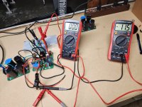
I tied both input leads together but had no load attached. The left DMM was hooked to the test points. The right DMM was hooked up to the output. I slowly ramped up the variac to 115AC. No reading at all on the left DMM and a reading of -11.5 mV on the right DMM. Both DMM's were set to the 200mV DC scale. Interestingly enough the LED on the amp board glowed bright red.
Even with my limited understanding I recognize the open circuit as there is no voltage present at the test points.
As one would expect, my dim bulb tester did not light up and both MOSFET's remained cold to the touch.
Any obvious places to begin looking? I double-checked my power connections just for good measure.
I would be grateful for any insights or suggestions. Please know that I may be away from my account from time-to-time today and probably won't have time to implement any suggestions until tomorrow morning. Thanks! Respectfully, Dave M.
I ran into a little bump in the road with my testing of the first amplifier board.
The set-up:
I tied both input leads together but had no load attached. The left DMM was hooked to the test points. The right DMM was hooked up to the output. I slowly ramped up the variac to 115AC. No reading at all on the left DMM and a reading of -11.5 mV on the right DMM. Both DMM's were set to the 200mV DC scale. Interestingly enough the LED on the amp board glowed bright red.
Even with my limited understanding I recognize the open circuit as there is no voltage present at the test points.
As one would expect, my dim bulb tester did not light up and both MOSFET's remained cold to the touch.
Any obvious places to begin looking? I double-checked my power connections just for good measure.
I would be grateful for any insights or suggestions. Please know that I may be away from my account from time-to-time today and probably won't have time to implement any suggestions until tomorrow morning. Thanks! Respectfully, Dave M.
Attachments
It looks like everything is working. If I understand you correctly the left DMM is connected across the output Source resistor to measure bias current and the right DMM is measuring DC offset.
The 0mV probably means the pot had not been turned enough to allow current to flow. Slowly adjust it to get about 26mV for 120mA across 0.22ohm. The 11mV offset is normal range.
The MOSFETs are cold because no current. At 120mA they will be a little warm as dissipating about 2.75W each.
If DC offset goes above 0.5V something is wrong and turn off and debug.
Good luck!
Thanks X. I appreciate the advice. I'll let everyone know the results tomorrow.
Best. Dave M.
Best. Dave M.
Hi guys,
An update on my amp board testing and hopefully a clue as to the source of my bias problem.
As suggested by X, I powered everything back up and turn the adjustment screw on the trim pot. Left, right, many turns, still nothing. I have DC offset but no bias current.
As a little experiment I replaced the amplifier board with the other board. Same exact problem. I had -10.0 mV offset but no bias reading. I doubled checked to make sure my left DMM was making good contact with the test points labeled "bias."
This got me thinking that the issue must be something basic that I screwed up. Then when examine my flying leads I noticed that the Vbe multiplier lead had a twist in it. This would effectively result in it being wired backwards. Could this cause my lack of current to the MOSFET's?
If anyone has any insights I'm totally open to feedback. Thanks in advance. Respectfully, Dave M.
Attachments


Definitely yes if the VBE multiplier is backwards. It is the master controller of the bias current. You have a BD139 which is pinout ECB, flipped is connected BCE so all wrong. Please correct and it should fix it. Luckily nothing blew up. But please check to see if the pins follow ECB. I can’t tell from photo how it is attached at the BD139 as it is obscured.
Hello fellow forum members,
Thought I'd post an update on my FH9HVX build.
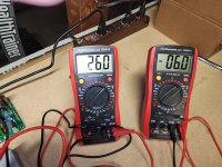
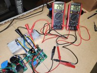
The problem I was having with lack of bias current did indeed boil down to my error in wiring the Vbe multiplier female receptacle backwards. Once corrected I was able to bring bias up to recommended levels and tweak the settings as the MOSFET's warmed up. I ended up with a reading of 26.0 mV of bias on the left channel with a DC offset of -6.0 mV. The right channel settled in at 26.0 mV of bias with DC offset of -8.5 mV. Is it normal to have negative DC offset readings?
I am having some issues with the SFP soft-start board. If I am unable to debug on my own I will post the details in the proper SFP thread.
Lastly, I purchased a Dissipante 4U steel enclosure to house my project and that was delivered yesterday. I am looking forward to exploring my layout options. I've encountered a few bumps in the road, but otherwise feeling pretty stoked about my first stereo amp build. Respectfully, Dave M.
Thought I'd post an update on my FH9HVX build.
The problem I was having with lack of bias current did indeed boil down to my error in wiring the Vbe multiplier female receptacle backwards. Once corrected I was able to bring bias up to recommended levels and tweak the settings as the MOSFET's warmed up. I ended up with a reading of 26.0 mV of bias on the left channel with a DC offset of -6.0 mV. The right channel settled in at 26.0 mV of bias with DC offset of -8.5 mV. Is it normal to have negative DC offset readings?
I am having some issues with the SFP soft-start board. If I am unable to debug on my own I will post the details in the proper SFP thread.
Lastly, I purchased a Dissipante 4U steel enclosure to house my project and that was delivered yesterday. I am looking forward to exploring my layout options. I've encountered a few bumps in the road, but otherwise feeling pretty stoked about my first stereo amp build. Respectfully, Dave M.
Attachments
Congrats. Yes, proper orientation of the BJT transistor in the Vbe multiplier is paramount!
Negative DC offsets with the numbers you state are completely fine. What you should look for is the absolute value. 50 to 100mV or more should be addressed imho by proper matching of the transistors and circuit design overall. Thankfully you have none of that.
The 4U/300 enclosure should be just fine (if not a little overkill) for this circuit. Your heatsinks at the quiescent currents recommended (80mA to 200mA) will only get barely warm.
Best,
Anand.
Hi UncleMud,
Congrats on solving the lack of bias current issue. When you said vbe multiplier was wired backwards, I knew that had to be it.
As Anand said, -6mV is nothing to be worried about and normal. It can be either positive or negative. If you have a transistor tester, and a bunch of the input LTP BJTs, you can check them to find two with an exact Hfe match and this may bring the offset down even lower. You can then bend the legs so that the two flats of the TO92 bodies touch each other and cover that with shrink tube to thermally bond them together. This will help the DC offset track better with temp. Of course, no practical difference from 6mV to 0mV DC offset. 6mV offset is 30uW of dissipation in an 8ohm speaker.
What is the problem on the SFP? You can post questions in the SFP thread if you want - or maybe tell us the quick story here. It’s generally a very straightforward circuit to get working.
Last edited:
Good morning DIY'ers,
Progress report on my FH9HVX build.
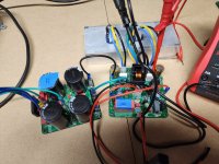
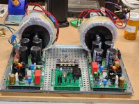
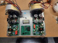
Now that I've moved on to mounting my PCB's to the chassis. I'm making good progress. However, I do have a concern. As you can see from the pics, space is at a premium with the dual mono option.
My specific concern is that in order to fit everything with this layout choice, I have the PSU and amplifier pcb's basically touching each other. I can't imagine this is ideal. Are the traces sufficiently recessed that it's a non-issue? Could I put Kapton tape along the edges? (Or is that a cheap hack for a poorly designed layout?) I'm sure this is a basic question but this is my first amplifier build.
I could mount the amplifier boards on the heat sinks if I have to. I don't have a good reason not to, as they are already drilled and tapped. Thanks in advance for any experience/advice you may have.
Dave M.
Progress report on my FH9HVX build.
Now that I've moved on to mounting my PCB's to the chassis. I'm making good progress. However, I do have a concern. As you can see from the pics, space is at a premium with the dual mono option.
My specific concern is that in order to fit everything with this layout choice, I have the PSU and amplifier pcb's basically touching each other. I can't imagine this is ideal. Are the traces sufficiently recessed that it's a non-issue? Could I put Kapton tape along the edges? (Or is that a cheap hack for a poorly designed layout?) I'm sure this is a basic question but this is my first amplifier build.
I could mount the amplifier boards on the heat sinks if I have to. I don't have a good reason not to, as they are already drilled and tapped. Thanks in advance for any experience/advice you may have.
Dave M.
Attachments
@UncleMud
That looks like you have a very nice build going there! Just make sure all you V+/V-/G connections on the boards are insulated. The space between the electrolytic caps on the All Cees board and the amp board where you will have insulated Fast On connections may be a bit tight - hard to tell from here.
I personally like to mount amp boards directly onto the heatsink in order to relieve space inside the enclosure (for extras if needed). But that’s a personal preference. This is up to you as you already are using Mosfet snubbers for the build. Make sure the connections to the Molex connectors are nice and tight - i.e. not loose. If in doubt, direct solder but since you already tested/biased the main amp boards with the Mosfets on the snubber pcb’s, I am thinking you are good to go.
The pcb’s touching - I don’t see that as a problem.
It would be most preferred that the L-brackets where the toroids are mounted don’t touch the front panel. There should be an airgap. This is to prevent shorted turns. This is less likely given that the front panel is anodized. If in doubt use some nonconductive piece of adhesive/plastic/kapton/something to prevent that! The L-brackets should be tightly adhered to the steel sub plate with locknuts. In other words, if you were to pick this amp up and shake the hell out of it, the Toroids don’t physically move or move as little as possible! In some builds, I have seen two L-brackets per toroid primarily for this purpose. This might not be too much of an issue for DIY builds but in commercial builds, the Toroids can shake loose in shipping - so keep that in mind.
Make 150% sure that the final nut on the chassis ground connection is a locknut. Think of it this way. Imagine if your amplifier was thrown from a building (which is what shipping companies do!), everything might break but the final connection between IEC ground and chassis ground should never break. Make sure that that wire is of a sufficient gauge. Don’t use a tiny 24 gauge wire. I usually go for 16 or 18AWG, whatever comfortably fits. I am happy to see that your chassis ground connection is a dedicated connection. All too often I see diy’ers attaching the chassis ground to the IEC terminal mount or a Toroid center mounting bolt which is completely wrong. It should be a dedicated connection solely for that purpose. It’s a safety thing!
I am very pleased you are using a terminal board with a cover - that’s great for safety, and accidental hand waving, cat crawling, etc…
Best,
Anand.
Last edited:
Hi UncleMud,
Anand is spot on. I would mount amp PCBs on heatsinks to free up space as well. Keep amp PCBs close to heatsink to minimize wire length to MOSFETs.
Were you planning on using RTR SSR speaker protection PCBs?
Those are now in stock.
Great work!
Anand is spot on. I would mount amp PCBs on heatsinks to free up space as well. Keep amp PCBs close to heatsink to minimize wire length to MOSFETs.
Were you planning on using RTR SSR speaker protection PCBs?
Those are now in stock.
Great work!
Thank you XRK and Anand for weighing in with your thoughts. You've both been a ton of help to me and I'm grateful.
I've decided to make some changes based on concerns I already had as well as your feedback. First of all the amp boards will be moved to the heat sinks to free-up space. More importantly, the L brackets are coming off and being replaced with a much heavier pair I considered but passed on. I don't think there is any chance of the toroids touching the front panel, but I was already on the fence about the strength of the current brackets. I want my build to be rugged and 100% safe. Regarding the wire I plan on using for wiring to safety earth I purchased some high quality 16 AWG so I should be good.
Lastly, I do plan on using the RTR speaker protection boards I ordered from X. Sounds like they should arrive in plenty of time. I plan to mount them directly to the back panel if space allows. I may be offline for several days while I make these changes. I'll keep everyone up-to-speed though.
Respectfully, Dave M.
- Home
- Group Buys
- FH9HVX - Budget Conscious 100w Class AB for Lean Times