Yes.Remind me which speakers you built? Was it 10F/RS225 FAST TL?
I played the a bit louder today, up to 75%. That was sufficient for my needs. I am happy.
🤘
Thanks.

Yes.
I played the a bit louder today, up to 75%. That was sufficient for my needs. I am happy.
🤘
Thanks.
Getting ready to fire mine up for the first time this week, just a couple more wires to do. Do you @nikpolini do you happen to recall if counter-clockwise lowered or raised the bias?
No sorry, not off hand, but a little fiddle and you will see right away which way it is... Make small adjustments once you get close to desired value and allow it a few minutes to stabilise before adjusting again...Getting ready to fire mine up for the first time this week, just a couple more wires to do. Do you @nikpolini do you happen to recall if counter-clockwise lowered or raised the bias?
Good luck, but really if it is like mine it is a very (luckily) uneventful process...
Nik
I seem to have a short, thankfully I'm using a dim bulb tester so the one amp board I plugged in should be fine.
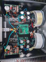
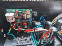
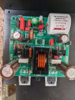
All boards were freshly pulled from the chassis and cleaned with acetone and iso prior to turning it on. Before connecting an amp board to power, I tested the power supplies. All supplies turn on and pass the dim bulb test without a short. I'm using Antek AS-2238 transformers, wired in series. Poking around with a DMM both PSU boards show that the V- has 0ohms to ground. If I back things up, remove the power connections to the amp board, it will pass the dim bulb test and all PSU's will run.
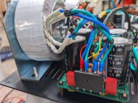
I've attached some pictures, happy to take plenty more. I'm not really sure where to begin troubleshooting this, I am hopeful someone has some ideas for me.
Thanks in advance!
All boards were freshly pulled from the chassis and cleaned with acetone and iso prior to turning it on. Before connecting an amp board to power, I tested the power supplies. All supplies turn on and pass the dim bulb test without a short. I'm using Antek AS-2238 transformers, wired in series. Poking around with a DMM both PSU boards show that the V- has 0ohms to ground. If I back things up, remove the power connections to the amp board, it will pass the dim bulb test and all PSU's will run.
I've attached some pictures, happy to take plenty more. I'm not really sure where to begin troubleshooting this, I am hopeful someone has some ideas for me.
Thanks in advance!
Attachments
The behavior of 0ohms on the V- output isn't consistent and more often shows a higher resistance like 1K ohms, when I see it at 0ohms, if I pull the DMM lead off and reconnect it, it starts to rise. Anyway, I've removed the bottom plate from the chassis, which leaves me with easier access to the boards and wiring for troubleshooting.
I guess i assume I am doing something incorrect as opposed to a faulty component as both sides have the same behavior.
I guess i assume I am doing something incorrect as opposed to a faulty component as both sides have the same behavior.
Last edited:
Here you go.
I thought maybe the wiring going to the small capacitance PSU boards for the SSR protection boards may be a culprit, but disconnecting the 3 wires into those boards and leaving all 3 leads open in the air didn't change anything.
I thought maybe the wiring going to the small capacitance PSU boards for the SSR protection boards may be a culprit, but disconnecting the 3 wires into those boards and leaving all 3 leads open in the air didn't change anything.
Attachments

Ok, those are the PSU, but you said they are working fine when no amp boards connected?
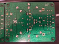
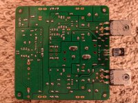
Can you post pics of the underside of the amp board too please?
Nik
Can you post pics of the underside of the amp board too please?
Nik
Thanks guys 🙂
Nik that's correct, the little black boards are low capacitance PSUs, the other boards with the large caps are the main PSUs. All 4 PSU's function just fine without an amp board connected.
This probably helps someone with a bigger brain than I, but I reassembled it a few minutes ago, and the issue of 0ohms at V- moved to 0ohms at V+, the only thing I might have done differently reassembling is reversed the order in which I connected the trafo secondaries. I have had a feeling this whole time it has something to do with my trafo secondary windings but here I am at a loss. I'm not colorblind, but let's pretend for a minute that I am, how would a color blind person identify the proper wires for center tapping a dual secondary trafo? **edit - I checked back at one of my earlier pics, I did reverse the transformer secondaries when reassembling, regardless unless I am wrong either way is still wired in series correctly.
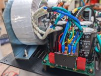
More pics for your review. Need to step away for a couple hours but I'll be back.
Nik that's correct, the little black boards are low capacitance PSUs, the other boards with the large caps are the main PSUs. All 4 PSU's function just fine without an amp board connected.
This probably helps someone with a bigger brain than I, but I reassembled it a few minutes ago, and the issue of 0ohms at V- moved to 0ohms at V+, the only thing I might have done differently reassembling is reversed the order in which I connected the trafo secondaries. I have had a feeling this whole time it has something to do with my trafo secondary windings but here I am at a loss. I'm not colorblind, but let's pretend for a minute that I am, how would a color blind person identify the proper wires for center tapping a dual secondary trafo? **edit - I checked back at one of my earlier pics, I did reverse the transformer secondaries when reassembling, regardless unless I am wrong either way is still wired in series correctly.
More pics for your review. Need to step away for a couple hours but I'll be back.
Attachments

BH,
Where do you have the small DC protection psu outputs connected? I do not see them connected to the protection boards?
Where do you have the small DC protection psu outputs connected? I do not see them connected to the protection boards?
Hi Bloqhead,
Don’t worry we will figure this out.
Please check the following:
1. Disconnect the All Cee’s from amp and use DMM in ohms mode to check continuity of +ve rail to GND and -ve rail to GND. This can be done by probing D on N channel and D on P channel (pin 2) pins sticking through or at the Fastons for PSU input. How many ohms? If under 1k ohm you have a solder bridge short, a dead MOSFET (ESD zapped), or incorrect MOSFET sex P/N swapped. Your solder joints look clean. The P channel looks correct but I can’t see N channel. My suspicion is you zapped it with static. Did you discharge your hands or wear an anti static wrist strap when installing the MOSFETs? It is winter and dry air prone to zapping.
2. With trafo secondaries disconnected from All Cee’s PSU check continuity. Between the secondaries that you think are connected. If this is good, there is a very remote chance that Antek mislabeled the phasing of the secondaries or miswired them completely. This would cause a short and it would normally blow a fuse. But since you have a dim bulb tester it doesn’t.
3. You have swapped All Cee’s PSU wire polarity? Photos look good.
4. You have a pin hole on the silicone insulator and a piece of metal Burr is poking through and touching mosfet heat tab. If using ceramic insulator pad ignore this comment.
Good luck! My guess is you have a ESD zapped MOSFET. Antek will test their trafos before sending out so I doubt wires are mislabeled - but remote possibility.
Last edited:
Each one connects right now to an LED that will mount in the front panel. I was waiting to get the amp boards figured out before I whip up some cables to connect the SSR boards.BH,
Where do you have the small DC protection psu outputs connected? I do not see them connected to the protection boards?
Hi Bloqhead,
Don’t worry we will figure this out.
Please check the following:
1. Disconnect the All Cee’s from amp and use DMM in ohms mode to check continuity of +ve rail to GND and -ve rail to GND. This can be done by probing D on N channel and D on P channel (pin 2) pins sticking through or at the Fastons for PSU input. How many ohms? If under 1k ohm you have a solder bridge short, a dead MOSFET (ESD zapped), or incorrect MOSFET sex P/N swapped. Your solder joints look clean. The P channel looks correct but I can’t see N channel. My suspicion is you zapped it with static. Did you discharge your hands or wear an anti static wrist strap when installing the MOSFETs? It is winter and dry air prone to zapping.
2. With trafo secondaries disconnected from All Cee’s PSU check continuity. Between the secondaries that you think are connected. If this is good, there is a very remote chance that Antek mislabeled the phasing of the secondaries or miswired them completely. This would cause a short and it would normally blow a fuse. But since you have a dim bulb tester it doesn’t.
3. You have swapped All Cee’s PSU wire polarity? Photos look good.
4. You have a pin hole on the silicone insulator and a piece of metal Burr is poking through and touching mosfet heat tab. If using ceramic insulator pad ignore this comment.
Good luck! My guess is you have a ESD zapped MOSFET. Antek will test their trafos before sending out so I doubt wires are mislabeled - but remote possibility.
- Both MOSFET D pins show ~5Meg between D pin and 0V. Same ~5Meg between 0V tab and either +ve tab or -ve tab. I believe this is what you want me to test. It did read 0ohms for a split second and then jumped to 5Meg and stayed there. I think this test indicates the MOSFETs are ok? I'm happy to remove them and test with a transistor tester. I generally discharge my hands but don't wear a static strap, I will have to start just in case.
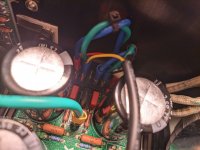
- Trafo secondaries measure as expected with continuity between each pair (image attached showing each pair in a different colored circle).
- Polarity is good, quadruple checked that when wiring
- I've used ceramic so we are good here
Attachments
amp is good, trafo is good, then you must have a short or bad connection on your All Cee’s.
With amp disconnected and trafo disconnected. Does +ve or -ve on All Cee’s register 0 ohms to GND?
With amp disconnected and trafo disconnected. Does +ve or -ve on All Cee’s register 0 ohms to GND?
amp is good, trafo is good, then you must have a short or bad connection on your All Cee’s.
With amp disconnected and trafo disconnected. Does +ve or -ve on All Cee’s register 0 ohms to GND?
Trafo disconnected from All Cee's. +ve to 0V (or PE) starts around ~100ohm and rises to ~1Meg. -ve to 0V (or PE) starts around ~100ohm and rises to ~1Meg. 0V to PE is a stable ~50ohms, which should be expected due to the SL15 47003 NTC.
I just had a thought, this also exposes the major novice in me. I'm testing with a dim bulb tester, when testing with the amp board disconnected, the bulb flashes on then goes extremely dim and stays that way. I then connected one amp board, and tested with the dim bulb tester again, the bulb flashes bright and stays bright. My understanding is that a dim bulb tester when there is a short will prevent the amp from turning on, but with the one amp board connected everything appears to receive power in the chassis. Is it possible that due to only connecting one amp board the dim bulb tester behaves differently than expected?
Last edited:
Hmmm...
This says that the fault occurs when the MOSFETs switch on and are basically shorting out actively. This means the Gate is driving it to full tilt and your bias settings are off.
Check the resistors around the BD139 temp compensation sensor, check solder joints for cold solder or shorts, check values of resistors. What is the DC offset at the speaker output read when you power it up? What is the voltage across the 0.22R Source resistors? There is something off with the DC setpoints then.
I think we are on to something. If you recall earlier I was asking about setting the bias pot fully counter-clockwise prior to firing up, I ended up setting the pot fully counter-clockwise. My first turn on with the amp board had a DMM connected to a 0.22R source resistor test points and the DMM showed 150mV before I turned things off and started down the path we are currently on.
It'll take me 30 min or so to reassemble the amp so I can test things with power, going to also set the bias pot fully clockwise unless you think otherwise.
It'll take me 30 min or so to reassemble the amp so I can test things with power, going to also set the bias pot fully clockwise unless you think otherwise.
That might be it. Set to half point on pot if unsure. Fully clocked one way or other has 50% chance of failure. 🙂
bloqhed,I think we are on to something. If you recall earlier I was asking about setting the bias pot fully counter-clockwise prior to firing up, I ended up setting the pot fully counter-clockwise. My first turn on with the amp board had a DMM connected to a 0.22R source resistor test points and the DMM showed 150mV before I turned things off and started down the path we are currently on.
It'll take me 30 min or so to reassemble the amp so I can test things with power, going to also set the bias pot fully clockwise unless you think otherwise.
I think after this experience you might consider getting a bench supply - I have 2 of them, one for low voltage circuits from HP and another for higher voltage. They are extremely useful. I always bench test every circuit prior to installing it in the main enclosure. Think of it as a "variac" for the DC supply end of things (I only use dim bulb testers now for old tube/solid state amps that walk into the lab; most other times, I use a variac - extremely useful as well).
Usually when I test and I do not know which way the pot should be turned, I slowly increase the DC supply voltage on the bench supply and watch to see if the current draw across the source resistors is increasing dramatically. If it is, I turn the voltage down, adjust the pot and try again.
Good sleuthing though! I enjoy reading the problem solving situations such as this and I'm sure others will benefit from reading about it as well.
Fingers crossed you should be making music soon 👍.
Best,
Anand.
Last edited:
Great advice on bench testing with known PSU.
I have a bench supply but my problem is lack of bench space! 🙂
I have one of these Instek GPC 3020 linear ones:
https://www.ebay.com/itm/2640302755...Y9mcKZ3Rq-&var=&widget_ver=artemis&media=COPY
Built like a tank.
I have a bench supply but my problem is lack of bench space! 🙂
I have one of these Instek GPC 3020 linear ones:
https://www.ebay.com/itm/2640302755...Y9mcKZ3Rq-&var=&widget_ver=artemis&media=COPY
Built like a tank.
- Home
- Group Buys
- FH9HVX - Budget Conscious 100w Class AB for Lean Times