Nice work!
I would recommend heatsinks for V124 and V129, they are dissipating more than 1/2 watt (especially for longevity). This is assuming you are going for the >50V rail option. If you are at +/-35V, you might be fine since the dissipation will be less, but still…. Put some heatshrink over your input NPN transistors to minimize differences from a thermal standpoint.
I used the 5.2mm tip on my Hakko soldering iron and plenty of flux for the inductors.
I just nearly finished my 1st board as well…
Best,
Anand.
Thank you Anand. Yes, I am waiting to buy some 3mm machine screws to attach the heat sinks. I forgot to mention that in my post, but Thank You for noticing that.
Also, after I populated the board I decided to mount the output MOSFETs on helper boards so I may need to remove a couple of resistors from the board. I haven't investigated that issue fully.
Sounds like you are making good progress on your build. Wishing you a good outcome. Cheers. Dave M.
Also, after I populated the board I decided to mount the output MOSFETs on helper boards so I may need to remove a couple of resistors from the board. I haven't investigated that issue fully.
Sounds like you are making good progress on your build. Wishing you a good outcome. Cheers. Dave M.

Looking good, one suggestion is to check your solder joints, looks like the iron might not have been hot enough, because a number of component holes don’t have the solder wicking up thru the top side. Could be a frustrating search for a cold solder joint when you get to the point of applying power and you find there’s an issue.
Bullit does have a good point, although I figure you soldered from the bottom side. Perhaps reheat several of the joints but apply flux first to enhance flow. I always use flux whether its SMD or through hole.
Best,
Anand.
Best,
Anand.
After thinking it over I've decided that I will inspect my solder joints and reflow anything that looks suspicious. I'm also going to solder all exposed leads from the top as well. That should reduce my risk of an open circuit. I would rather put in the time now when I have access to the boards. Thanks again for the heads up.
I have the week off, and I'm feeling motivated to finish some projects (FH9HVX and XSD's primarily). Hopefully it warms up in Minneapolis enough so that the space heater helps with garage-work on the XSD's.
About a year or more ago I tried to tap an M3 hole and failed miserably. Following some guidance from vunce and gary s, I went at it today and who knew that if you do it properly, it's actually kind of easy. I would say the hardest part is cleaning up the tap magic. It's just a dry fit with no thermal paste for now as I have to assemble the other board. Going with dual antek AS-2238's, dual All Cee's, an SFP, a pair of X's SSR speaker protection boards. I've had everything I need down to way too many molex connectors sitting here for a long time now, so it's time I get this bad boy going.
The case is from aliexpress, exterior dimensions are 430*311*150mm, interior 330*300*142mm, heatsinks are 300*145*50mm. Originally the plan was for a similar chassis but only 120mm in height, however after deciding to go dual mono, I just don't see a way to make that happen, I'll use the shorter chassis for something else.
To power the SSR boards I'm going to use a small dedicated transformer, I was thinking an AN-0112 (10VA, dual 12VAC secondary). Will that be enough current for the SSR boards X? Or will I need to bump it up to an AN-0212 (25VA, dual 12VAC secondary)?
Hi Bloqhead,
Nice work! 12v is not enough as you will need 15v trafo for the SSR as you need 18vdc minimum since the voltage regulator on board needs 3v above 15v. It’s easy to connect the ultra low capacitance PSU board to one of the main rail trafo secondaries vs getting a separate trafo. The chassis looks great.
Good luck!
Thanks X, I'll do that. The low capacitance PSU board J2 COM goes to the 0V on the All Cee's right? Then no D1 or D2, and voila I am good to go.
Hi X and all,
Quick update, I'm almost done, powered up and set bias at 26mv and output at 3.5mv offset.
Happy with that, now just to do the output wiring and input wiring.
Cheers.
Quick update, I'm almost done, powered up and set bias at 26mv and output at 3.5mv offset.
Happy with that, now just to do the output wiring and input wiring.
Cheers.
Attachments
Last edited:
Actually, I am a bit worried the heatsinks are not big enough for the 40vac trafo, turns into 60vdc... Maybe I should use a 35 or 30v trafo. Heatsinks are 150x75x50...Hi X and all,
Quick update, I'm almost done, powered up and set bias at 26mv and output at 3.5mv offset.
Happy with that, now just to do the output wiring and input wiring.
Cheers.
Throughs?
You are dissipating 14W per channel at idle (116mA x 60v x 2). That’s not an unreasonable value for the size of the heatsinks you have. But if you plan at playing very loud higher powers for extended time, it may get warm. But 55C is a long ways to go from maybe 32C idle. I would use it and spend some time playing music at levels you like and monitor temp. Change to bigger heatsinks only if it’s a problem. Better to leave trafo alone and drop bias current to 80mA. Should still sound very good and reduce idle dissipation to 10W per channel and feel cooler.
Very nice work. Congrats!
Very nice work. Congrats!
Thanks X.You are dissipating 14W per channel at idle (116mA x 60v x 2). That’s not an unreasonable value for the size of the heatsinks you have. But if you plan at playing very loud higher powers for extended time, it may get warm. But 55C is a long ways to go from maybe 32C idle. I would use it and spend some time playing music at levels you like and monitor temp. Change to bigger heatsinks only if it’s a problem. Better to leave trafo alone and drop bias current to 80mA. Should still sound very good and reduce idle dissipation to 10W per channel and feel cooler.
Very nice work. Congrats!
How hot would be too hot when playing Pink Floyd too loud? Lol...
Seriously though what would be the max temp of the MOSFETs and also the results of too hot, do they thermally shutdown, or just go POOF!
Cheers.
A good indicator is the temperature of your heatsinks. If they are consistently above 50°C, time for bigger heatsinks or lower the voltage.
Yes, at 55C you can’t touch your hestsinks more than 2 seconds without feeling great discomfort. If you touch the sensitive skin of your inner fore arm, you may even get a burn. It’s best to keep heatsinks below 50C or below but technically they can be as hot as 55C. The mosfet body temp is 85C or lower is a good temp to aim for.
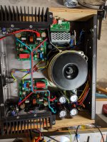
I am slow yes, but chipping away at things. Just finished up getting all the boards mounted, this week I can start the wiring.
Unless I am wrong, I should turn the bias pots all the way counter clockwise, short inputs, test first with a dim bulb tester, if that passes I should be ok to start biasing. I do have a 5A variac, is there a guide I can read somewhere on how I test an amp with that?

Unless I am wrong, I should turn the bias pots all the way counter clockwise, short inputs, test first with a dim bulb tester, if that passes I should be ok to start biasing. I do have a 5A variac, is there a guide I can read somewhere on how I test an amp with that?
Very nice mate. What size are those trafo?I am slow yes, but chipping away at things. Just finished up getting all the boards mounted, this week I can start the wiring.
Unless I am wrong, I should turn the bias pots all the way counter clockwise, short inputs, test first with a dim bulb tester, if that passes I should be ok to start biasing. I do have a 5A variac, is there a guide I can read somewhere on how I test an amp with that?
View attachment 1128473
Nik
- Home
- Group Buys
- FH9HVX - Budget Conscious 100w Class AB for Lean Times