Hey RickRay,
Thanks for the response. That sounds like a good plan. Maybe I will get better with practice. You brought up a good point about ordering extras. I dropped one on the floor pretty much first thing out of the gate. Cheers.
Thanks for the response. That sounds like a good plan. Maybe I will get better with practice. You brought up a good point about ordering extras. I dropped one on the floor pretty much first thing out of the gate. Cheers.
Here is the paste I use, made by ChipQuik.
.jpg")
Yea, I know it is out of date, however it is still working perfectly, so I continue to use it.
Yea, I know it is out of date, however it is still working perfectly, so I continue to use it.
LMAO, me too, that's why I order a few extra. Practice does make perfect, having a tube of flux for parts with more than 2 pads is EXTREMELY helpful. I have successfully soldered SMD PIC chips, but it is a REAL pain.
The FH9HVX has optional SMD parts. You can also use the through hole equivalent at the same spot. I think they are silver mica compensation caps (TH) vs NP0/C0G (SMT).
RickRay said it well.
For a few parts like this, a soldering iron and even regular solder can be used.
Here is the process.
Add a small bump of solder with iron on one pad. Place part on that bumpy pad and hold in place with tweezer pushing down on top of the part. While applying pressure, apply solder iron tip to corner of part solder bump. Solder should melt and wet part and remove iron. Wait 5 seconds for it to harden. Then take solder and iron and touch opposite corner to wet solder. That should do it.
Or use paste on both pads, place part, apply pressure from top and touch ends with solder iron.
Thanks X,
I will give that strategy a try as well. With practice I'm sure I will find a method that works for me. It's good to know I have the through-hole option as a back up if necessary.
I will give that strategy a try as well. With practice I'm sure I will find a method that works for me. It's good to know I have the through-hole option as a back up if necessary.
Key with either method is to find something to hold part down with while you touch soldering iron. I usually rotate board in-between soldering sides of part.
I have found "X's" method works extremely well with parts with more than two pins. I cover all pads liberally with flux, then use his method to apply solder to each pin. First one pin one corner then an opposite corner to make sure part is in right position, then hit rest of pins.

UncleMud, I do a variation of RickRay's description but doing SMD work by hand is only easy if the parts are big enough, they have exposed solderable pads or finger-like projections, e.g., SOIC op-amps and you have some room to get your soldering iron tip to where you need it to go. I like a small chisel tip instead of a round pointed tip. I just put flux paste onto PCB pads, place the component onto the fluxed pads and hold it there with finely pointed tweezers, put a dap of regular solder onto my iron's chisel tip then touch one side of pad/component junction. The solder should flow well because of flux paste and the chisel tip can make contact with both the component end and the soldering pad. Don't worry if it doesn't look pretty at first and don't,worry about doing the other side at this point. I'll mount all the SMD components (usually the resistor or capacitor packages) like this then come back to do all the other sides. I put a small dab of flux on the un-soldered side and bring your clean chisel tip & thin solder to that side. The solder should flow right in. You can clean up/fix any solder joints (later) by just putting more flux on and using a cleaned soldering tip. You won't overheat most components unless you keep the soldering iron on the component too long. You can use soldering paste but it has a supposed shelf life and I found buying a whole syringe of the stuff, and then only using a bit of it, to be wasteful. Follow RickRay's directions for removing what you've done and cleaning the pads before trying again.@UncleMud I usually have better luck cleaning the board, and attach SMD components one at a time. I place a small dollop of water-wash solder paste on the two pads, place the part with tweezers, hold in place with tweezers, and then touch with the solder iron at 325-350 just long enough to melt the solder. i've had pretty good luck with that method. I would use solder braid to remove the solder on those 4 parts, then use solder iron to move the parts off the pads, clean pads with solder braid and start over. If you overheat the part, no problem, use a new part. I usually order a few extra of SMD parts just for that reason, not to mention the ones get dropped and not found.
If your whole PCB is SMD components the oven is really the only way to go. X's technique of using a hot plate under the PCB, and a hot air gun over the top of the component is also a viable way to go for complicated SMD work (if one doesn't have an oven).
I wish you luck
Pete
Thanks everyone. I have a lot of new ideas now to practice with. It might take me a while to put them to use as I need to order some Flux and extra parts. Onward and upward.
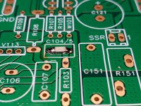
I thought I would give an update on my attempts to solder the surface mount capacitors on my FH9HVX build.
I followed RickRay's direction on removing the old parts and prepping the pads. I used plenty of Flux and followed X's instructions for soldering the SMD's. I also took the additional step of taping the board down to the top of my work bench with painters tape for greater stability. This worked AWESOME!
Thanks to everyone who offered tips and suggestions, they were much appreciated.
Dave M.
Attachments
Hi folks,
Wondering if any forum members could clarify something for me regarding resister value requirements at R141. In the thread I saw posts (447 & 449) indicating that this position should have resistor(s) capable of dissipating 1w. In the parts I ordered I received 2 envelopes of resistors designated for R141. One resistor was 1/4 watt 22.1 K ohms 1% and one was .6watt 22K ohms 1%. Both are metal film composition not carbon. Are these close enough in value to "piggy-back" in parallel to achieve a higher wattage? I am familiar with Ohm's law but not sure about this specific application. Thank you in advance.
Wondering if any forum members could clarify something for me regarding resister value requirements at R141. In the thread I saw posts (447 & 449) indicating that this position should have resistor(s) capable of dissipating 1w. In the parts I ordered I received 2 envelopes of resistors designated for R141. One resistor was 1/4 watt 22.1 K ohms 1% and one was .6watt 22K ohms 1%. Both are metal film composition not carbon. Are these close enough in value to "piggy-back" in parallel to achieve a higher wattage? I am familiar with Ohm's law but not sure about this specific application. Thank you in advance.
Attachments
When I built the generic version, not this revised version, I used 1/4w resistors for everything, except the 0.22r I used 3w. It is a low current and voltage position, so use whichever one you want to.
Edit according to your schematic - I would use the 0.6w one's for R103 and R111, since they are coded CMF (Vishay Dale) and generally 0.6w, so you should have Three 22k0 or 22k1 resistors for the board R103, R111 and R141, and yes either 22k0 and 22k1 can be used
Edit according to your schematic - I would use the 0.6w one's for R103 and R111, since they are coded CMF (Vishay Dale) and generally 0.6w, so you should have Three 22k0 or 22k1 resistors for the board R103, R111 and R141, and yes either 22k0 and 22k1 can be used
Hi everyone,
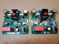
Just a quick update. Making slow but deliberate progress. Looking for a small flamethrower to finish soldering the coils on the power inductor.
What a treat to work with these pcb's. Between the stuffing guide and the silk screening I felt assembly went well. My next step is to hop over to the All Cees thread and begin planning my power supply.
Attachments
- Home
- Group Buys
- FH9HVX - Budget Conscious 100w Class AB for Lean Times