I generally use 2n5401 as a replacement, but would sub in 2n5551 for the MPSA42 while I'm at it, if you have any in the circuit.What would be a good replacement for mpsa92?
Thanks

Thanks for the offer Bullistang. That’s a good option to swap with 2N5401 - same pin outs EBC. The current gain Hfe on MPSA92 is about 25 while the 2N5401 is about 100. It will probably work though but watch out for oscillations.
I have most of the components needed for this amp, but finding them in my drawers takes a lot of time.
And after that I try to remember when and where I bought them from ,
very annoying when I question the authenticity of some stuff I don't remember about.
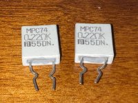
Like the resistors in this picture.
@bullittstang
Thank you , I found some KSP92 transistors.
And after that I try to remember when and where I bought them from ,
very annoying when I question the authenticity of some stuff I don't remember about.
Like the resistors in this picture.
@bullittstang
Thank you , I found some KSP92 transistors.
Attachments
My apologies for not reading the whole 60 page thread... but are there real-world (not spice) test results for THD, IMD, etc from one of these amps?
Those look legit to me - the cheap ones from eBay/Aliexpress generally don't have the kink. Those pictured I have only purchased from Mouser or DK.I have most of the components needed for this amp, but finding them in my drawers takes a lot of time.
And after that I try to remember when and where I bought them from ,
very annoying when I question the authenticity of some stuff I don't remember about.
Like the resistors in this picture.
@bullittstang
Thank you , I found some KSP92 transistors.
OK, Just checking something.
The MPSA92-AP that is in the Mouser Project/BOM is obsolete, but there are plenty of other MPSA92 and also over at E14 there are 100000+ available.
What's the differences?
https://au.mouser.com/c/?q=mpsa92&instock=y
https://au.element14.com/multicomp/mpsa92/transistor-pnp-to-92/dp/1574392
Looks like the specs are the same?
Cheers.
Hello Forum Community Members,
Greetings from frosty Minnesota. I am a new builder who happily discovered the DIY forum a few months ago. I am a beginner. I have built several small headphone amplifiers which I am happy with, including the Whammy. Several years ago I attempted to build a class B power amplifier based on a design by G. Randy Slone but shelved the project when the fuses kept blowing.
I recently purchased the FH9HVX boards and one All Cees board from XRK's store and have been busy working at parts acquisition. I went with the premium parts list and at this point, there are 5 components I am having trouble sourcing. I have taken the time to read the entire thread, taking notes along the way. With that information in hand I think I can make an informed decision on choosing substitutes for the two resistors in question. However the other 3 parts I am unsure of, and would like to ask for some guidance. I have included possible alternatives to the 3 parts along with their respective technical data sheets. Any guidance from more experienced builders on the suitability of my choices and/or where else to look for substitutes would be appreciated.
Thank you in advance for your time and patience. I am excited to get started after hearing such great things about this amp. Respectfully, Dave M
1. (R143) Vishay Metal Film Resistor 4.75 ohm 1w 1%
2. (R144) Vishay Metal Film Resistor 10 ohm 2w 1%
3. (V121) MCC Bipolar Transistor BJT 300v 300mA
*Alternative: Multicomp Pro Transistor- Newark #08N8078 Mfg. #MPSA92
4. (C121,122) Nichicon Aluminum Electrolytic Capacitor- Radial Leaded
*Alternative: Nichicon Aluminum Capacitor- Digikey #493-14895-ND Mfg.# UBW1J470MPD
5. (C181) KEMET Safety Capacitor 300vac 0.022uF10% Y2 15mm
*Alternative: KEMET Safety Capacitor Mouser #80-R413I222050T0K Mfg. #R413I222050T0K
Attachments
MPSA92 is in stock.
https://www.mouser.com/ProductDetail/Diotec-Semiconductor/MPSA92?qs=OlC7AqGiEDm8RQC/IPFdxg==
A 5% 4.7ohm 1W is fine:
https://www.mouser.com/ProductDetail/Vishay-BC-Components/PR01000104708JR500?qs=3M67XevNmDLNpXGccBvCkg==
A 5% 10ohm 2W is fine:
https://www.mouser.com/ProductDetail/Vishay-BC-Components/PR02000201009JR500?qs=7reVrgTiN3YqjE9KUsFQcQ==
47uF Nichicon cap is in stock:
https://www.mouser.com/ProductDetail/Nichicon/UBW1J470MPD?qs=Wu4QelNNmeM4%2Bz2Kbk05Wg==
22nF film cap is in stock:
https://www.mouser.com/ProductDetail/KEMET/R413I222050T0K?qs=sGAEpiMZZMsh%2B1woXyUXj9kQnrMN1UR3ILVZQIaFCJ8=
Maybe you should try searching on Mouser for your parts if not at Digikey.
The items I asked about were listed as unavailable or on backorder on my Mouser BOM. That is why I was looking elsewhere. Sorry for the hassle. I really appreciate your time. Respectfully, Dave M.
No need to apologize Dave,
I believe you can replace the mspa92 from Diotec https://www.mouser.com/ProductDetail/Diotec-Semiconductor/MPSA92?qs=OlC7AqGiEDm8RQC/IPFdxg==
with ksp92 from Onsemi https://www.mouser.com/ProductDetail/512-KSP92TA,
cheaper and available.
I believe you can replace the mspa92 from Diotec https://www.mouser.com/ProductDetail/Diotec-Semiconductor/MPSA92?qs=OlC7AqGiEDm8RQC/IPFdxg==
with ksp92 from Onsemi https://www.mouser.com/ProductDetail/512-KSP92TA,
cheaper and available.
@xrk971,
Thanks for the prompt delivery of the boards (FH9HVX, SSR, Mosfet snubbers, and panel mount BTSB). I’m constructing some BOM’s as we speak.
It appears that due to the size of the FH9HVX boards being about 100mm square, my original plan to use a DIYAUDIO store based 3U chassis is just a smidgen too small with the brackets installed. No worries, I’m happy to use a 4U/300 for the build. Given the higher heat dissipation capabilities of the 4U/300, and my desire to bias this amplifier to the max 250mA, is +/- 50V the highest voltage rails you would recommend for this design? The heatsinks can definitely handle more than +/- 50VDC @ 250mA (25 watts dissipation) and my PSU caps are rated at 80VDC. Even at 25 watts dissipation, we are only talking about 91 deg F (assuming 25 deg C ambient) on 4U/300 heatsinks (0.31 degC/watt). In addition, I’ll be placing the MOSFETs (FQA versions) in the most optimum locations for convection and the use of snubbers will eliminate any chance of oscillation due to the slightly longer wiring. The plan is to use a 400VA custom Toroidy with quad secondaries and 40,000uf/channel (20,000uf per rail/ch). At 250mA we are talking 2 watts peak/8 ohms, 1 watt peak/4 ohms in Class A before transitioning to Class B.
Next question, if I have 0.25 ohm/5 watt source resistors, is that close enough to the design center of 0.22 ohms? Since we are adjusting the bias using a pot on the Vbe multiplier circuit, I figure 0.25 ohms should be close enough to work?
Thanks again, this looks like a fun design. It will be my first application of your panel mount BTSB (w/-6dB settings !!!) and SSR. With that it will be a truly universal Class AAB amplifier with 4 ohm drive capabilities. Interesting how I used the same FQA MOSFETS in my Alpha Nirvana yet this is a completely different application. Clearly my build won’t be “Lean” but frankly they never are 😎.
Best,
Anand.
Last edited:
Hi Anand,
If you have enough heatsinking, this amp can handle +/-57v rails without having to redo the DC set points. At 250mA bias current that is 29W per channel. A good number for a 4U chassis. The 0.25ohm source resistors are fine if you don’t want to use 0.22R. Although try to use non inductive ones - no wire wound. Bulk metal like KOA BPR or metal thin film Panasonic ERX.
Looking forward to seeing your amazing build. The BTSB will be slick looking here and neat to see a -6dB mod.
In case you don’t have a soft start - I have the SFP with a solid state relay. You will have a complete XRK Audio amp. 🙂
Good luck!
Btw, at +/-57v you can get up to ~175wpc no problem.
X,
Thanks! I think I will stick with +/- 55VDC as the design goal to allow for situations of line voltage variation (up to 125VAC) since I don’t have any intrinsic voltage regulation in this amplifier, just an all C supply. This is unlikely to happen at least in my house where it seems tightly regulated at 120VAC +/-1 VAC.
Conservatively, I’ll ask for 400VA w/40VAC secondaries.
Best,
Anand.
Hey Forum members,
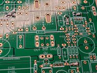
So I started on my FH9HVX project. My first foray into SMD soldering was wildly unsuccessful. As much as it pains me to attach the following picture it's necessary if I'm going to get this right.
I applied solder paste before placing the components. I used a portable heat gun with the temp set to 301C and the airflow at 50%. Unfortunately, what I ended up with were 4 sets of cold solder joints. In a couple cases the components didn't even adhere to the pcb.
Not to be deterred, I warmed up my soldering iron to 350C and attempted to resolder the SMD's by that method. I believe in that case my temp. may have been too high.
I am an older gentleman with aging eyes and some fine motor tremors which certainly didn't help. I think if I am going to continue working with SMD's I may have to devise a home-built reflow oven where everything can be set-up before heat is applied.
Now, for those of you who have hung in there with my lengthy post, my questions; do you think I should just start over with a new pcb? Since only 4 components have been soldered does it pay to try testing my connections for continuity?(I know this is usually a non-starter due to the multiple interconnecting circuits).
Finally, any tips on SMD soldering that have worked for you? Thank you in advance for your knowledge and time.
Dave M.
Attachments
@UncleMud I usually have better luck cleaning the board, and attach SMD components one at a time. I place a small dollop of water-wash solder paste on the two pads, place the part with tweezers, hold in place with tweezers, and then touch with the solder iron at 325-350 just long enough to melt the solder. i've had pretty good luck with that method. I would use solder braid to remove the solder on those 4 parts, then use solder iron to move the parts off the pads, clean pads with solder braid and start over. If you overheat the part, no problem, use a new part. I usually order a few extra of SMD parts just for that reason, not to mention the ones get dropped and not found.
- Home
- Group Buys
- FH9HVX - Budget Conscious 100w Class AB for Lean Times