Hi X and other builders,
I purchased some 2 line to 4 line connectors for hooking up the transformer secondaries to the All Cee's psu and also to have 2 AC wires to connect to the low capacitance psu for the SSR speaker protection. This worked for me, and was relatively easy to install, but I was thinking of doing the following in the paragraph below, while reassembling the amp trying to chase down hum problems.
I would tie each secondary wire together with another wire for the low cap psu, crimp them into a faston connector, and attach to AC input of the All Cee's psu. This will give 2 wires to the All Cee's psu and 2 wires for the AC input of the low cap psu. Also takes up less space and hopefully prevents other ground loop or grounding problems.
Any reason not to do this?
Thanks for the help
Yes, you can do exactly what you describe. That’s how I got my secondary for the low capacitance PSU for the SSR speaker protection.
Bloqhead,
Sounds like a fantastic setup - fully loaded! Yes, move the snubber resistors to the little boards for best results. This is an awesome amp and you will love the sound.
I feel like I must be missing something, probably something obvious. Pardon my ignorance in the following questions.
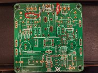
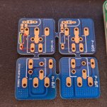
On the FH9HVX boards, current can't flow from V123 or V129 to V132's gate pin unless R132 is populated. If I move R131 and R132 to the snubber helper boards, do I put a jumper in place on the FH9HVX amp boards? On the blue MOSFET helper boards, pin 3 of the Molex connector has continuity (red line) to the gate pin on the MOSFETs, and I assume the snubber resistor would go where I drew the yellow line. Would the snubber resistor even do anything at this point?
I attached pictures to help visualize what I am thinking. On the picture of the amp boards I circled the two resistors I assume are the snubbers.
Attachments
Sorry about that, I think you have a good point. The blue snubber board provides points to install an RC snubber between the gate and Drain but the gate stopper resistor needs to go on the main PCB. The snubber boards for the Alpha Nirvana (tombstone shaped) are different and have gate stoppers near the pins.
So just install the 220R gate stopper on the main PCB and connect wires to the snubber board.
So just install the 220R gate stopper on the main PCB and connect wires to the snubber board.
No worries! Thanks for the reply. I plan to keep the wires quite short and mostly only using the snubber boards so I have a little breathing room with my hole tapping.
Just make sure it’s a high quality non inductive resistor. Go with a slightly different value if needed. 12ohms or 8.2ohms etc it’s all ok as most of signal goes through the inductor.
Awesome XRK, thank you!
So to confirm in-stock "best case" - my options for same HQ non-inductive precision Vishay resistor :
Vishay CPF 3watt 10ohm 1%
Vishay CPF 2watt 12ohms 1%
Would the 10ohm 3 watt be the preference? Or a 12ohm with the same watts value? (Part interested in just better understanding the Thiele Network.)
Appreciate the help!
Any of those should be fine. It won’t be more than a 1W necessary in most cases. This resistor absorbs HF oscillations so 12ohm is more conservative and technically, safer.
Shoot looks like R143 from that Mouser BOM is also now out of stock for an indefinite length of time. The 4R75 1w CMF.
They have the following in stock in the CMF Industrial series:
4R75 1/2W
5R 1W
4R 1.5W
4.99R 1.5W
5R 1.5W
Will any of these work? Or is it better to switch to a different series and stick with exactly 4R75 here?
There are some Vishay CPF series in 4R75 1W in stock.
They have the following in stock in the CMF Industrial series:
4R75 1/2W
5R 1W
4R 1.5W
4.99R 1.5W
5R 1.5W
Will any of these work? Or is it better to switch to a different series and stick with exactly 4R75 here?
There are some Vishay CPF series in 4R75 1W in stock.
Last edited:
Or put two 4.7ohm in series. Or just use 4.7ohm single. It should be fine. It’s only a backup filter in case you have a funky load. Some people run amps without them.
If I'm using a Micro-audio SMPS with dual extra cap boards for PS, what parts do I need from Mouser besides the amp parts?
Right now I have:
-Power switch
-IEC power entry (no switch, no fuse)
-extra filter caps for SMPS
I have binding posts and RCA jacks already. Am I forgetting anything to build this out? Do I need any additional NTC Thermistors or safety-rated caps?
Right now I have:
-Power switch
-IEC power entry (no switch, no fuse)
-extra filter caps for SMPS
I have binding posts and RCA jacks already. Am I forgetting anything to build this out? Do I need any additional NTC Thermistors or safety-rated caps?
Maybe SSR speaker protection circuit? The MicroAudio SMPS uses a low voltage remote on/off that will need a small front panel latching switch. You can even make it lighted. Those round stainless ones work well.
Where on the PCB do the test points (X1031-X1034) go?
The pads for bias.
Ah I see, thanks bloqhed.
Anyone have a part number for heatsinks (for V124 & V129) that fits in the space available? Preferably a clip on one, mounting hardware is always a pain I'd like to avoid if possible on lower-power transistors. Mouser doesn't have the one on the BOM.
Anyone have a part number for heatsinks (for V124 & V129) that fits in the space available? Preferably a clip on one, mounting hardware is always a pain I'd like to avoid if possible on lower-power transistors. Mouser doesn't have the one on the BOM.
- Home
- Group Buys
- FH9HVX - Budget Conscious 100w Class AB for Lean Times