There is no signal time delay. The output signal responds immediately as soon as the input is applied. But the phase shift causes waveform distortion (linear distortion), for instance, the zero-crossings appear later (or earlier, if you use a phase advance circuit). You cannot say the signal is delayed, it isn't. You could only say that some specific "markers" (by lack of a better word) on the waveform appear delayed or advanced like zero crossings or amplitude max and minimums.
Jan Didden
Jan Didden
MikeB said:[snip]Such a real timedelay would be introduced by long wires or digital
processing, not by RC or RL.
Mike,
In my understanding, ALL "delays" in real world audio amp circuits are only due to phaseshifts and as such do not constitute real delay. But if you would use very long cables, very long wrt to signal periodicity, then there may be delays, ie that it takes some time from application of the input until there appears any output reaction. Correct?
Jan Didden
Hi Jan,
I have the same understanding, but delays introduced by length of
wires are minimal, a whole meter creates a delay of ~3.3ns, in
audioterms negligible, for a computer a desaster.
I am not familiar with the effects inside semiconductors...
Mike
I have the same understanding, but delays introduced by length of
wires are minimal, a whole meter creates a delay of ~3.3ns, in
audioterms negligible, for a computer a desaster.
I am not familiar with the effects inside semiconductors...
Mike
We could consider propagation times in semiconductors, but at such high frequencies signal is shunted by internal capacitances without delay anyway.
This is just a bad idealisation of what actually happens. Fisrst: your 'time constant' is not constant at all, it's quite curved when you plot it against frequency. Second: altough it only changes a little from the origin up to f=1/(2*pi*R*C), it tends towards zero above that frequency!!
Believe me, I know these facts very well because I have extensively used phase shifters as a cheap alternative to simulate signal delays in the analog domain for active crossovers in multi-way horn-loaded systems. With phase shifts you can only simulate far from ideal delays that are only effective in a limited frequency range (and vanish above that range). However, phase shifts allow for phase/time correction and nearly optimum summing between horns in the small overlapping frequency range required by 24dB/oct crossovers. Furthermore, horns show pure delays but they also show non-linear 'time constants' so you end up compensating one non-linearity with another.
let sinewawes of different frequencies pass through RC integrating circuit. Transition of the RC output voltage through zero line will be always shifted (delayed) of dT = RC,
This is just a bad idealisation of what actually happens. Fisrst: your 'time constant' is not constant at all, it's quite curved when you plot it against frequency. Second: altough it only changes a little from the origin up to f=1/(2*pi*R*C), it tends towards zero above that frequency!!
Believe me, I know these facts very well because I have extensively used phase shifters as a cheap alternative to simulate signal delays in the analog domain for active crossovers in multi-way horn-loaded systems. With phase shifts you can only simulate far from ideal delays that are only effective in a limited frequency range (and vanish above that range). However, phase shifts allow for phase/time correction and nearly optimum summing between horns in the small overlapping frequency range required by 24dB/oct crossovers. Furthermore, horns show pure delays but they also show non-linear 'time constants' so you end up compensating one non-linearity with another.
off topic:
Hi Michael
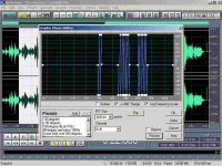
I just applied a weird phase shift in cool edit to a sweet jazz song. The slopes are wicked inplicating delays to certain frequencies, which is obviosly hearable. After a minute or so I felt a real ear ache. Seems as a new audio mass destruction weapon. If you want I'll send you an mp3 with and without phase shift.
Phase shift curve:
Hi Michael
I just applied a weird phase shift in cool edit to a sweet jazz song. The slopes are wicked inplicating delays to certain frequencies, which is obviosly hearable. After a minute or so I felt a real ear ache. Seems as a new audio mass destruction weapon. If you want I'll send you an mp3 with and without phase shift.
Phase shift curve:
Attachments
Hi darkfenriz !
Ah, i see, this way you apply dynamic phasehifts, this is of course
audible as you create harmonics.
I did it different, i applied FFT over a whole music, and rotated the
phasehifts per freq wildy (roating the complex numbers by sin/cos-matrix),
then retransformed. The wave was definitely changed, but listened
identical.
If you change phasehifts timedependent you get PIM.
But i am still interested in hearing that, can you mail me mp3 ?
michael AT synetic DOT de
Mike
Eva said:
Believe me, I know these facts very well because I have extensively used phase shifters as a cheap alternative to simulate signal delays in the analog domain for active crossovers in multi-way horn-loaded systems. With phase shifts you can only simulate far from ideal delays that are only effective in a limited frequency range (and vanish above that range).
I do believe you, because it is true what you are saying. My point of view is also based on everyday experience with multi-channel fast data acquisition of simultaneous transient signals or 3-phase voltages/currents during test of HV circuit breakers. And I cannot neglect different time-delays of BW limited sensors and measuring channels, in case their BW (DC - Fh) is different.
I know it is only semantic discussion and I do distinguish between propagation delay, transportation delay, delay lines and time delay due to limited bandwidth (RC integrating circuit) 😉
It looks like we are debating whether light "is" a particle or a wave... 😉
Phase shifts used for time alignment of course only work in a narrow frequency range because the "delay" (of waveform appearance) is frequency dependent.
But, to Jan, as to whether to call phase shift a form of delay in the first place - if it can be used for time alignment, well, I think there is some semantic latitude here.
Besides, a thought experiment - imagine you generate a single impulse, say a sharply windowed sine of a few cycles. You send it through 16 RC filters. The phase shift is zero (or 16*90=4*360 degrees, or zero modulo 2pi). Will that impulse now arrive with some delay after the original impulse sent through a straight wire? I believe one can call that a delay.
Had the signal in this experiment been a periodic one, it would have mattered none at all. In a periodic signal "delay" makes little difference to the information contained in it, neither group delay nor phase shift. A steady state signal has very little information content - just the one contained in one cycle. As a result it may be expressed as magnitude and phase in a single datum line.
Information can only come from a series of improbable (non predictable) transients. And in such a series, the position in time of zero crossing and apex of a series of nonperiodic impulses must matters - whether altered by phase shift or group delay. Of course it may often not be audible.
Eva's experience is interesting re: inaudible phase shifts. It may matter where and how they were applied. For all I know even trained musicians were unable to tell the kind of instrument, when the initial transient was cut off the recording - apparently the harmonic structure of the initial transient specifically matters for this. Also, it seems the appearance in time of harmonics in an instrument makes a large difference in playability. It seems that on some violins the tone "appears" to "lag" and in others, it appears to "precede" (!!) the stroke of the bow of the musician - due to exactly when and how strongly the harmonics appear apart from the fundamental.
Anyway, on one of my test CD's I always reliably fail to detect a group delay of supposedly 7 m worth of offset in the bass region...
RC circuit especially for Eva
I have prepared the RC circuit demonstrating constant group delay up to certain frequency. The example shows RC circuit with R = 1kOhm, C = 1uF, i.e. time constant RC = 1 ms. -3dB frequency of amplitude characteristics is 167 Hz.
Three characteristics are shown, amplitude, phase and group delay. From group delay, one can see that up to some 20 Hz (i.e. 1/8 of F(-3dB)) the group delay is constant and equals to 1ms which equals the RC time constant (who would have said that 😉 ). All the frequencies below 20Hz (for example 0.001Hz, 0.01Hz, 1Hz, 10Hz) are delayed of the same time, i.e. RC. This causes significant problems during multichannel measurements with different BW of sensors, in case that one start to magnify the record.
Attachments
PMA:
Then again, this is not a true time delay because you can revert the effects of phase shift from any lowpass RC filter with a zero thus nulling its 'time constant' and getting back the original waveform with no delay (and then you can place a pole at a known higher frequency so that all transducers show a much smaller and equal 'time constant').
On the other hand, there is no way to revert a delayed signal and go back in time, you will always sense the offending signal too late.
Unfortunately the zero (derivative) tends to magnify noise and interference in industrial environment.
I define a delay as constant vs. frequency. A real delay could be e.g. 5 seconds in a sampled system.
Group delay is defined (or so I have read) as -d(fi(omega))/de(omega) where fi(omega) is a function that describes the phase shift in a system. Omega is 2*pi*f.
So calling an all pass filter a delay line is IMHO not correct, since a delay is constant vs. frequency and the all pass filter exhibits a phase shift. I also find it incorrect to talk about delay in any analogue filter, but correct to talk about group delay.
\Jens
MBK said:[snip]But, to Jan, as to whether to call phase shift a form of delay in the first place - if it can be used for time alignment, well, I think there is some semantic latitude here. [snip].
Mike, yes true, life is quite comfortable even if one mixes phase shift with delay 😉
The reason why I wanted to bring this up was that many people think that "feedback appears after the fact, therefore cannot work". It does work, and it DOES NOT appear after the fact. As such, the feedback appears at the same moment the error appears, and is taken into account immediately. But because of the phase shift it gets less and less effective as freq rises. But is does not come after the fact. I thought that distinction is important; we wouldn't want people to buy the wrong amps just because they misunderstand delay! 😀 😀
Jan Didden
The reason why I wanted to bring this up was that many people think that "feedback appears after the fact, therefore cannot work".
Yes I have seen this stated by people who should know better. But then maybe their marketing wrote it.
The above assertion can be refuted easily by means requiring no math or other technical understanding. In deed, no words are necessary: just turn on the nearest amplifier, extend an index finger and point.
EVA's discussion of RC filters can be reinforced by "reducto ad absurdum" -- namely if it were true than RC filter truly caused a time delay in the ordinary meaning of the words, would not an RL filter constitute a time machine?
sry guys... i was kind of irritated the other day... mostly due to myself not being able to formule such clear sentences like Janneman just did....congrats Janneman, very cleary put.😉
tschrama said:sry guys... i was kind of irritated the other day... mostly due to myself not being able to formule such clear sentences like Janneman just did....congrats Janneman, very cleary put.😉
There's nothing so practical as a really good theory.😎
Jan Didden
sam9 said:
EVA's discussion of RC filters can be reinforced by "reducto ad absurdum" -- namely if it were true than RC filter truly caused a time delay in the ordinary meaning of the words, would not an RL filter constitute a time machine?
😀
Delay and feedback
While genuine delay devices are described mathematically in a different way than lumped component emulations (exp(-s.tau) instead of polynomial quotients), they can fake them fairly well within a restricted frequency range. The rationale is to *approximate* an as linear as possible phase/frequency relationship within that range.
Tektronix used to build lumped component delay lines (scores of miniature inductors and trimmers, see why they were so expensive !!) to display pretrigger events some 30+ years back.
In either case, the end result is the ammount of correction provided by feedback decreases with increasing fequency. The math shows this precisely, while the physical meaning is in fact the correction comes late. The higher the frequency (i.e. the more significant the delay) the less effective is the corrective action.
As to how significant this is, as usually it depends. What the designer targets is a minimum garanteed amount of correction (more precisely sensitivity attenuation) within a certain restricted working frequency band.
Another issue of concern is - when delay (or phase shift if you want) is significant within the working band even meeting design goals - is how the amplifying chain copes with the transient condition.
I undertand Graham's concern, as exemplified by his "First Cicle Distortion" has to do with this. Actually, a well designed amplifier with no slew rate problems within the working band and maximum input signal level, should emerge from the test unscathed (for normal signals).
An amplifier that for whatever reasons shifts operating bias (except the output stage if not class A) depending on signal level, is bound to have serious trouble in this department.
Rodolfo
Hi, Janneman,
Like always, you make me more confused 😀
Who is making the phase shift?
I can see that signal from the left transistor has to make some journey to get to the output node. It has to pass VAS transistor and output stage transistor (+drivers). Is this the one who makes phase shift?
Hi, FORR,
OK, so you understand or agree with EVA's explenation about RC phase shift. I assume from the first quote, you think that internal C (B-E/B-C) of a transistor is a myth to be causing a problem in this discussion.
Which C do you think fit in EVA's theory? Miller Cap? If I don't use miller cap, my amp won't have phase shift? Naaa.......don't make sense. Or is it you mean intrinsic C that is inherent in every 1/4W resistor? Or is it parasitic C of PCB tracks?
Like always, you make me more confused 😀
Offcourse it does not 😀 In audio amplifier, connection between output node and inverting point of differential is just a voltage divider. The base of the right transistor of the differential got to receive what happened in the output node at instance. Resistor divider don't make phase shift/delays.It does work, and it DOES NOT appear after the fact. As such, the feedback appears at the same moment the error appears, and is taken into account immediately.
Who is making the phase shift?
I can see that signal from the left transistor has to make some journey to get to the output node. It has to pass VAS transistor and output stage transistor (+drivers). Is this the one who makes phase shift?
Hi, FORR,
LUMANAUW
"If an amp having signal passing more of this B junction, you will get more
delay, because these capacitance have to be charged/discharged."
This is a demonstration of how to make myths grow in audio.
(note : not every body agrees that the cited amplifiers are audibly the best).
EVA
"The output of any RC circuit reacts inmediately to input changes but with
non-constant time-dependent amplitude, as opposed to what happens when a signal
is delayed, where any change in the input appears at the output after some time.
Since any input change is not delayed in RC circuits, the output is just
reflecting the instantaneous value of the input signal with time-dependent
attenuation."
This is the most understandable explanation of the whole story.
OK, so you understand or agree with EVA's explenation about RC phase shift. I assume from the first quote, you think that internal C (B-E/B-C) of a transistor is a myth to be causing a problem in this discussion.
Which C do you think fit in EVA's theory? Miller Cap? If I don't use miller cap, my amp won't have phase shift? Naaa.......don't make sense. Or is it you mean intrinsic C that is inherent in every 1/4W resistor? Or is it parasitic C of PCB tracks?
janneman said:There is no signal time delay. The output signal responds immediately as soon as the input is applied.
Jan,
this is well demonstrated by group delay response in
http://www.diyaudio.com/forums/showthread.php?postid=694246#post694246
The output responds immediately (high frequencies, zero group delay), but badly distorted (linear distortion as you said, small output amplitude). After some time, when settled (i.e. equivalent of low frequencies and "slow" input signal changes), the output is delayed with constant group delay. This, when measured, is seen as time delay, regardless how we name it.
- Status
- Not open for further replies.
- Home
- Amplifiers
- Solid State
- Feedback delay & distortion