AmpsLab are using TDA7250 in there amplifier. Maximum output current is quite similar to LM4702... 5mA 😉 So we have good base to build powerful amplifier. They are using Sziklai style output section:
http://www.ampslab.com/tda7250cfp.htm
http://www.ampslab.com/tda7250cfp.htm
I agree that an emitter follower is indeed an appropriate solution, but I was hoping for something a little more elegant. I was leaning toward a complimentary feedback pair, but I was a little hesitant since I would like to add a few more pairs of transistors to the output stage to make it capable of driving harder loads, and I haven't quite gotten the "triple" CFP to take multiple output transistors. I know that this is not a new problem, nor have I really tried hard to get it to work, so I guess I just haven't gotten it to work YET! 😀
Edit: Woopsie! Looks like I didn't take a close look at the schematic. At first glance I thought it was a simple emitter follower.
Edit: Woopsie! Looks like I didn't take a close look at the schematic.
At first glance I thought it was a simple emitter follower.Inverted "Daulington"
This output has intrigued me - I may try it. The negative thermal coefficient of the lateral mosfets helps keep them thermally stable.
http://www.ne.jp/asahi/evo/amp/J49K134/report2.htm
This output has intrigued me - I may try it. The negative thermal coefficient of the lateral mosfets helps keep them thermally stable.
http://www.ne.jp/asahi/evo/amp/J49K134/report2.htm
dshortt9 said:OR perhaps the 2sk215/j78 driving transistors?
Why not a single pair of MOSFETs for a good start? 😉
My LM4702 PCB 😉
An externally hosted image should be here but it was not working when we last tested it.
Re: lm4702 output
I putted one Dracula amplifier board into your package 😉 It's double sided and hard to manufacture home way.
Few posts forward:
http://www.diyaudio.com/forums/showthread.php?s=&threadid=79322&perpage=5&highlight=&pagenumber=5
I think that Sziklai style output section can be a good choice - but first I wont to try MOSFETs here... They can be placed into my board without any modifications.
steven344 said:We ordered some from you,Do you have a board layout for the dracula amp?
I putted one Dracula amplifier board into your package 😉 It's double sided and hard to manufacture home way.
steven344 said:What do you think of using this type of output
Few posts forward:
http://www.diyaudio.com/forums/showthread.php?s=&threadid=79322&perpage=5&highlight=&pagenumber=5
I think that Sziklai style output section can be a good choice - but first I wont to try MOSFETs here... They can be placed into my board without any modifications.
Hey Veteran, I am very interested in the LM4702 boards you made. I know the group buy is over but any possibility I can get the gerber files from you to fab my own board? What layout program did you use to make it? I use a copy of Protel I got cheap a while back.
Let us know any test results. I am curious if it just works like an LM3886 or if you have to do much tweaking to get it working good. Also VERY interested in how it sounds compared to a LM3886 or LM4780.
TIA
-SL
Let us know any test results. I am curious if it just works like an LM3886 or if you have to do much tweaking to get it working good. Also VERY interested in how it sounds compared to a LM3886 or LM4780.
TIA
-SL
lm4702 prototype
I just got 2 lm4702 amps working,they sound pretty good. I do feel the chip should be on a small heatsink it runs pretty warm.I built one witth darlington outputs and the other with Sziklai outputs.It does seems like the Sziklai sounds better .Some of the problems I had with Sziklai is the bias adjustment is more touchy.Its also very important to have all the pico farad caps in place or it will oscillate.I was going to use the lm4702 amp for sub amp with low pass filter and gainclone amp for small speakers.Photos to follow.
I just got 2 lm4702 amps working,they sound pretty good. I do feel the chip should be on a small heatsink it runs pretty warm.I built one witth darlington outputs and the other with Sziklai outputs.It does seems like the Sziklai sounds better .Some of the problems I had with Sziklai is the bias adjustment is more touchy.Its also very important to have all the pico farad caps in place or it will oscillate.I was going to use the lm4702 amp for sub amp with low pass filter and gainclone amp for small speakers.Photos to follow.
Would you describe your Sziklai output? What driver and output transistors. What capacitance? etc... Same as the one in your post #28?
I'll second the heat sink comment. I have been running test boards sans heatsink, and they have gotten warmer than I would have liked. I clamped a small temporary heat sink to the chips and they run much cooler (duh). I think National dropped the ball on this one with regards to running without a sink--I think the chip gets too hot for comfort, even at moderate (~+/-35V) rails.
Use a small sink and be done with it.
Use a small sink and be done with it.
Attachments
Steven,
I noticed you cut off your biasing values! 😀😀
Thanks for sharing, and I think I really like this output configuration too. My CFP stage is a little different, but I think I will have to try yours and see how I like it.
David
I noticed you cut off your biasing values! 😀😀
Thanks for sharing, and I think I really like this output configuration too. My CFP stage is a little different, but I think I will have to try yours and see how I like it.
David
😀 I was just giving you a hard time! I thought it was pretty straight up what you intended.
Thanks again, though!
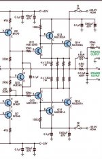
Quick question: I noticed you are using 4 parallel 1.5ohm resistors rather than a single .33 or .375 ohm resistor. Are you having any issues with overheating a single resistor, or are they behaving well despite any potential mismatches?
Thanks again, though!
Quick question: I noticed you are using 4 parallel 1.5ohm resistors rather than a single .33 or .375 ohm resistor. Are you having any issues with overheating a single resistor, or are they behaving well despite any potential mismatches?
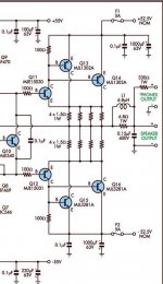
lm4702
This schematic is from a discrete amp project from silicon chip website,but I have seen this type of output in many amps when I used to repair audio equipment.You can use 1 resistor ,just make sure you have 100 pf from base to collector of driver or it could oscillate.
This schematic is from a discrete amp project from silicon chip website,but I have seen this type of output in many amps when I used to repair audio equipment.You can use 1 resistor ,just make sure you have 100 pf from base to collector of driver or it could oscillate.
lm4702
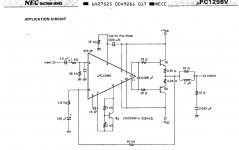
Fets may be the way to go with the lm4702 since they are voltage devices that wont load down the lm4702 5ma is not much to work with.I have used the upc1225,upc1270,upc1298 for many years as a driver IC with just a couple of outputs and bias transistor
Fets may be the way to go with the lm4702 since they are voltage devices that wont load down the lm4702 5ma is not much to work with.I have used the upc1225,upc1270,upc1298 for many years as a driver IC with just a couple of outputs and bias transistor
Attachments
- Status
- Not open for further replies.
- Home
- Group Buys
- Fast GB: LM4702 high power amp test board ;)