fets for lm4702
I would like to know what veteren thinks of using irfp240 and irfp9240 with the lm4702.I can get fqa19n20c and fqa12p20 from Fairchild which is their cross to IR parts
I would like to know what veteren thinks of using irfp240 and irfp9240 with the lm4702.I can get fqa19n20c and fqa12p20 from Fairchild which is their cross to IR parts
Re: fets for lm4702
I like IR transistors 😉 IRFP240/IRFP9140 will be quite good for start - similar Rds-on resistance and quite low input capacitance. Another pair of MOSFETs: 2SK1529/2SJ200.
steven344 said:I would like to know what veteren thinks of using irfp240 and irfp9240 with the lm4702.I can get fqa19n20c and fqa12p20 from Fairchild which is their cross to IR parts
I like IR transistors 😉 IRFP240/IRFP9140 will be quite good for start - similar Rds-on resistance and quite low input capacitance. Another pair of MOSFETs: 2SK1529/2SJ200.
An externally hosted image should be here but it was not working when we last tested it.
I'm also working on small boards with protection circuits for this amplifier. There are no such things integrated in LM4702 structure.
lm4702
Nice job on your boards,You may want to think about a rev b board set up for Complementary Sziklai Output,I tried this output with the lm4702 and like it better,it leaves room for more choices for output transistors.
Nice job on your boards,You may want to think about a rev b board set up for Complementary Sziklai Output,I tried this output with the lm4702 and like it better,it leaves room for more choices for output transistors.
MOSFETs are playing now - better and better with every minute ;D I will put them on a bigger heatsink and turn on the current.
An externally hosted image should be here but it was not working when we last tested it.
Looking pretty nice. What sort of test have you done? Any listening test? As I posted earlier in the thread, if there any change to get the PCB design files like Gerbers or will there be another GB? I'd like to try this amp out with FETs too.
TIA,
-SL
TIA,
-SL
Was thinking more about the LM4702 and this thread. Will protection circuits affect the sound or will they not have enough of an effect to be noticeable? Or do protection circuits not have any effect on the sound quality (good or bad) until they actually do their protecting?
Thanks for any info,
-SL
Thanks for any info,
-SL
Member
Joined 2002
veteran said:MOSFETs are playing now - better and better with every minute ;D I will put them on a bigger heatsink and turn on the current.
An externally hosted image should be here but it was not working when we last tested it.
Are you going to go for another group buy of these boards?
Re: lm4702
I was also thinking about some Sziklai style output for this amplifier - no problem making board for it 😉
Differential output voltage of the LM4702 is a little to small (I have max. 6.4V here) to pull out all the 'heat' from IRFP transistors (Vgs should be about 3.7 for each or more if you wont to work in 'flat class A') so I have to buy some 2SK1529/2SJ200. I want to keep this as simple as I can without adding another stage.
~SpittinLLama
Now, when I know that it works fine I can make another small GB.
What do you say for this board in two versions: MOSFETS and Sziklai output stage? There will also be PS board (8 diodes and place for big snap-in caps) and maybe small board with protection circuits.
steven344 said:Nice job on your boards,You may want to think about a rev b board set up for Complementary Sziklai Output,I tried this output with the lm4702 and like it better,it leaves room for more choices for output transistors.
I was also thinking about some Sziklai style output for this amplifier - no problem making board for it 😉
Differential output voltage of the LM4702 is a little to small (I have max. 6.4V here) to pull out all the 'heat' from IRFP transistors (Vgs should be about 3.7 for each or more if you wont to work in 'flat class A') so I have to buy some 2SK1529/2SJ200. I want to keep this as simple as I can without adding another stage.
~SpittinLLama
Now, when I know that it works fine I can make another small GB.
What do you say for this board in two versions: MOSFETS and Sziklai output stage? There will also be PS board (8 diodes and place for big snap-in caps) and maybe small board with protection circuits.
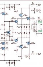
steven344, what do you think about one, universal board for this amp? Output stage can look like this:
Most of power transistors are in SOT93 and TO247 enclosures with standard pin-out (BCE / GDS). Configurations for this board:
1) T3 and T5 (or even T4 and T6 for double pairs) are MOSFETs. There are no T1 and T2 - only C and B pins are shorted.
2) As above but T3 and T5 are darlington transistors.
3) All transistors on this schematic are mounted = Sziklai style output.
4) T3/T4 are NPNs and T5/T6 PNPs. R3/R5 and R4/R6 - jumpers. This way we have symmetrical power darlingtons.
...
😉
An externally hosted image should be here but it was not working when we last tested it.
Most of power transistors are in SOT93 and TO247 enclosures with standard pin-out (BCE / GDS). Configurations for this board:
1) T3 and T5 (or even T4 and T6 for double pairs) are MOSFETs. There are no T1 and T2 - only C and B pins are shorted.
2) As above but T3 and T5 are darlington transistors.
3) All transistors on this schematic are mounted = Sziklai style output.
4) T3/T4 are NPNs and T5/T6 PNPs. R3/R5 and R4/R6 - jumpers. This way we have symmetrical power darlingtons.
...
😉
Re: lm4702 output
OK 😉 Do you have some pictures of working amplifier with this output stage? And how does it sound?
steven344 said:i was thinking more like this
OK 😉 Do you have some pictures of working amplifier with this output stage? And how does it sound?
lm4702
Yes ,But Im at work now,I have upload them when I get home.I used the set up from the schematic that way it lets you try different output transistors.Darlingtons are 2 transistors in the same package anyway.I think the bass is more controlled and there are not many high current darlingtons.
Yes ,But Im at work now,I have upload them when I get home.I used the set up from the schematic that way it lets you try different output transistors.Darlingtons are 2 transistors in the same package anyway.I think the bass is more controlled and there are not many high current darlingtons.
lm4702
With a driver transistor on your board with the 100 ohm on the collector plus 100pf base to emmitter,I put the outputs and emmitter resistors on a heatsink and ran wires back to the board.
With a driver transistor on your board with the 100 ohm on the collector plus 100pf base to emmitter,I put the outputs and emmitter resistors on a heatsink and ran wires back to the board.
lm4702
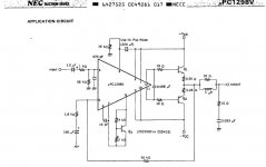
The lm4702 is just a voltage amp you can design the output stage anyway you want,darlingtons are the cheapest most simple way.Check out upc1225,upc1270 I have used these many years to build sub amps.You can use 2 bridged to get about 100watts
The lm4702 is just a voltage amp you can design the output stage anyway you want,darlingtons are the cheapest most simple way.Check out upc1225,upc1270 I have used these many years to build sub amps.You can use 2 bridged to get about 100watts
veteran said:steven344, what do you think about one, universal board for this amp? Output stage can look like this:
An externally hosted image should be here but it was not working when we last tested it.
Most of power transistors are in SOT93 and TO247 enclosures with standard pin-out (BCE / GDS). Configurations for this board:
1) T3 and T5 (or even T4 and T6 for double pairs) are MOSFETs. There are no T1 and T2 - only C and B pins are shorted.
2) As above but T3 and T5 are darlington transistors.
3) All transistors on this schematic are mounted = Sziklai style output.
4) T3/T4 are NPNs and T5/T6 PNPs. R3/R5 and R4/R6 - jumpers. This way we have symmetrical power darlingtons.
...
😉
That's not a bad idea. I had been playing around with different output board pairs to get the same idea. The only drawback that I can think of would be that the size of the universal board would be a little larger than necessiary. Still, that's definitely not a deal breaker, and the added flexability would be nice.
David
steven344, now it should be more clear.
Just few jumpers and you will be able to make your output stage 😉 I'm using 56pF caps on input and NFB - without them my amplifier is unstable without any source connected. The only nice darlingtons are the SAPs but they are hard to buy.
dfdye, maybe it won't be much bigger 😉 I can place transistors in front of LM4702 (mine is running quite hot so I will need a little heatsink for it).
An externally hosted image should be here but it was not working when we last tested it.
Just few jumpers and you will be able to make your output stage 😉 I'm using 56pF caps on input and NFB - without them my amplifier is unstable without any source connected. The only nice darlingtons are the SAPs but they are hard to buy.
dfdye, maybe it won't be much bigger 😉 I can place transistors in front of LM4702 (mine is running quite hot so I will need a little heatsink for it).
Thanks for the reply. Please post when another group buy comes up. I will be keeping an eye out for it. Also keeping up on this thread but I must admit I don't know enough to understand the differences between the different output stages shown (beside that they are different).
-SL
-SL
- Status
- Not open for further replies.
- Home
- Group Buys
- Fast GB: LM4702 high power amp test board ;)