Not impressed with the AliExpress product. Just weedy little Sot-23 driver transistors.
Nice to see my design in use
Nice to see my design in use
Hello Kosmic , i will be interested by one module , could you put all component , i am not equipped with small
I live in France
Merci in advance
I live in France
Merci in advance
Bon soir pioux
I might have advertised this somewhat unclear. The four printcard I have in spare is without components.
Now several months after my posting interest suddenly pops up. More to come of that and I might pull some strings.
I might have advertised this somewhat unclear. The four printcard I have in spare is without components.
Now several months after my posting interest suddenly pops up. More to come of that and I might pull some strings.
Hello Kosmic
I understood this, i just ask if that can be done , in all case i will be happy with one without component
Do this is possible
Merci Bruno
I understood this, i just ask if that can be done , in all case i will be happy with one without component
Do this is possible
Merci Bruno
Hello,
I would be very happy to acquire a replacement pcb for STK3102III to repair my beloved Philips FA960 amplifier. STKs purchased on Aliexpress fail after a few minutes or when I turn the amplifier back on. Pin 11 gives 0V instead of -1.8V.
Many thanks,
Evfit
I would be very happy to acquire a replacement pcb for STK3102III to repair my beloved Philips FA960 amplifier. STKs purchased on Aliexpress fail after a few minutes or when I turn the amplifier back on. Pin 11 gives 0V instead of -1.8V.
Many thanks,
Evfit
Hello greetings from Denmark.
Came across this thread some time ago because i accuired a SONY TA-F630ESD in a deal and this one was part of it.
It had the apparently well known issue with defective STK3102.
I left he unit for some time on the shelf but has just repaired it.
I am a retired electronics engineer doing some repais on accasion just for fun.
I thougt i would share what i did on this unit.
I thougt why not try to repair the original STK3102-III ? Could that be done ?
I took of the lid and exposed the internals . I traced the fault to be a faulty resistor , the one supplying the current mirrors. I managed with some surgery to bypass with a discrete resistor.
Based on the info in this thread i used app. 54kohm . Had to parallel two values i had to yield app. 54k , ideally i would have chosen two of the same value either in parallel or in series but i did'nt have suitable values.
I could have checked the non faulty channel but i was frankly afraid i might do damage to that channel so i avoided touching anything not absolutely nescessary .
With this repair the unit works again but i am not quite satisfied with the DC offset in either channels. The rigt channel app. 25mV and the repaired channel app. 60mV.
It apears that this discrepancy is in fact caused by the STK3102 transistors. I tried to change the resistor value to app. 50k and 60k and it did not change much. However the base voltages on the input differentials show large differences between the two channels and strangely the output voltage differential in the repaired channel seem nicely mirrored around GND potential whereas the other channel seem to have a much larger offset but the endresult on the speaker terminals is reversed .
Anyway the unit works , distortion at 10Watt , 8 ohm is < 0.001% in fact left is app. 0,0008% and right is app. 0,0007% .( idle at 7mV ).
So for now i chose to accept the result and see if it continues to work.
I could have chosen to do the same repair in the other channel to be proactive since i suspect the rootcause to be too high power dissipation in the affected thick film resistor but again it is delicate surgery and easy to mess it up but it is doable.
So if this is the typical issue it might be reparable in general.
Attachments
![20211106_111257[1].jpg](/community/data/attachments/907/907833-7ffb30fbb2183307e41bbe64b4fac554.jpg?hash=f_sw-7IYMw)
The mirror resistor value is not critical
The design pushes it way too hard. That is why my version now uses three resistors in series to spread the heat out
The design pushes it way too hard. That is why my version now uses three resistors in series to spread the heat out
I have a Philips FA960 with a STK3102III. Which is the best part to replace it with? are updated part explained in this post available? Thank you
Just an idea: JLCPCB makes quite inexpensive prototype PCB and they even have a single sided Aluminum option. (So the connector would need to be SMT.) Not sure how applicable it is but I thought I would mention it. It might be suitable for the replacement design and trying it with JLCPCB is very low cost. However soldering to the aluminum is obviously a different experience.
Please see the attached image. Note that you need to change the layout to single sided and no holes. (All SMT including the connector pins.)
Just FYI in case it helps someone.
Please see the attached image. Note that you need to change the layout to single sided and no holes. (All SMT including the connector pins.)
Just FYI in case it helps someone.
Attachments

Hello,I have a Philips FA960 with a STK3102III. Which is the best part to replace it with? are updated part explained in this post available? Thank you
I did a lot of checking and testing on my FA960, and I could not find the cause of the problem. The fake STK3102III chips (labelled 3810, or other numbers) keep failing after turning the amp on a few times.
So I set out to build the replacement STK designed by davidsrsb. I ordered the pcb from JLCPC (FR-4 and not aluminum, because I don't know how to modify the Gerber files provided by davidrsb). For the MMBT5401 and MMBT5551 transistors, there is currently a shortage at RS and Farnell, so I bought them from TME (Poland) made by a well known maker (ONSEMI). I bought the ZXTP5401 (ONSEMI) and the DTZ5551 (ONSEMI) from RS, aswell as the BAV99 diodes. I will start building the replacement STK when all the parts arrive and I will post the result.
For the FA960, you should check the type : is it a 220V 00R version, a 240V 05R or a 110-120-220-240 01R version (with voltage selector) ? If you have a 220V version and if you live in a country where the main is 230V, it should be better to switch your FA960 to 240V. This should help protect the STK from overvoltage. I have the 220V 00R version. To change it to 240V, I desoldered the wire conecting W902 to W876 on the power transformer and soldered it on W877. But I did that after after I stopped destroying STK's the one after the other. I don't know if it would have really helped.
Thank you for posting, I'm in the USA with a 120v model that I have enjoyed for 30 years until a few weeks ago...looking forward to your STK build.
I can do a version with SMT connector this weekendJust an idea: JLCPCB makes quite inexpensive prototype PCB and they even have a single sided Aluminum option. (So the connector would need to be SMT.) Not sure how applicable it is but I thought I would mention it. It might be suitable for the replacement design and trying it with JLCPCB is very low cost. However soldering to the aluminum is obviously a different experience.
Please see the attached image. Note that you need to change the layout to single sided and no holes. (All SMT including the connector pins.)
Just FYI in case it helps someone.
Ok. With your SOT-223 layout and the aluminum it will hopefully be reasonably cool and reliable/long life.
It does need to be a true single layer board and zero holes for JLCPCB aluminum. But it is only $2 (and then plus shipping) to try.
It does need to be a true single layer board and zero holes for JLCPCB aluminum. But it is only $2 (and then plus shipping) to try.
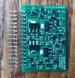
That is a neat soldering jobHere is my version of the replacement STK3102 designed by David. For the pin header, I used the pins from a discarded fake STK3201.
Here is the heat dissipation system I devised for the substitute STK 3102 :
- The thermal control system consists of two aluminum plates which enclose the STK3102. Conduction for heat removal is obtained by means of two thermal cushions sandwiching the STK3102. Thermal cushions are the excellent but rather expensive Gelid Solution GP-Ultimate 90X50X3.0mm cushions. A thickness of 2.0mm would probably have already been sufficient. The cushions are easily cut with a cuter. They perfectly mold the components of the STK3102 and ensure ideal thermal contact. On the photo, we see the rear face of the STK3102, green in color. The front face, component side, faces down and has already been pressed against the thermal pad and the first aluminum plate. The components (transistors, diodes, and resistors) are now embedded in the Gelid and are therefore in good thermal contact with this plate.
- A second thermal pad is applied to the rear face of the STK3102.
- The substitute STK3102 is now sandwiched by two thermal pads and two aluminum cooling plates.
- After mounting and welding the substitute STK3102, a bar is screwed on one side to the frame and glued on the other side to the aluminum plate to prevent any vibration of the device.
- After one hour of operation, the temperature of the substitute STK3102 remains stable at 35.8 °C. The current temperature in my workshop is around 14.6 °C). The temperature difference between the STK3201 and the environment is now only 21.2 °C.
- The Philips FA960 amplifier now works as before, with the sound that I love so much.
Last edited:
Hopefully that will work for many years.
If someone does modify the gerbers for the JLCPCB aluminum option they could extend the height of the board so that aluminum board has a "built-in" additional length of aluminum heatsinking.
If someone does modify the gerbers for the JLCPCB aluminum option they could extend the height of the board so that aluminum board has a "built-in" additional length of aluminum heatsinking.
See this thread
https://www.diyaudio.com/community/threads/stk3152-stk3102-clone-for-aluminium-back-pcb.380947/If you can agree on a bigger board, I will change the Gerbers for the single sided version
https://www.diyaudio.com/community/threads/stk3152-stk3102-clone-for-aluminium-back-pcb.380947/If you can agree on a bigger board, I will change the Gerbers for the single sided version
- Home
- Design & Build
- Parts
- Fake STK3152/STK3102