Did you ohm out your transformer secondaries? They are part of the bias and offset circuits. Lift one leg of R11 and R12 and check. Each winding should be about 28 ohms.
Thanks for the quick reply. Stupid question: I unsolder one side of R11 and R12 and attach the DMM to the unsoldered (separately) to test ohms while the amp is turned on? Also, is this done with the dim bulb tester or without?
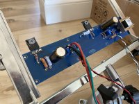
Just putting f6 boards together and noticed 10k ohm resistors are too large to fit pcb pads properly. Mouser part indicates they’re 1/4 watt. All the other 1/4watt on the boards are smaller and fit properly. Is this an issue or can I just bend leads as necessary? This isn’t a problem except where R7 and R9 get real close on one of the boards (see picture) I don’t see this as a problem but wanted to ask
Attachments

OFF!!
Thanks ZM. Just to confirm, am I checking R11/R12 on the F6 PCB or the PSU?
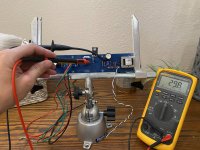
Attached are pics of the F6 w/ R11/R12 unsoldered on one side and a pic of my PSU with nothing in R11/R12.
Attachments
well, I'm sure that avdes..guru will answer that
I didn't read back, but I'm sure that lifting resistors while amp is ON Iznogood
I didn't read back, but I'm sure that lifting resistors while amp is ON Iznogood
To test transformer secondaries: power must be off and stay off!!
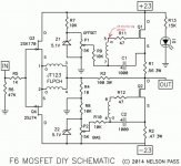
Lift R11 resistor leg off PCB as shown in schematic attached. This disconnects one end of the winding from everything else.
Measure ohms between PCB pad you just lifted the leg off of (common with JT123 pin 5) and JT123 pin 7.
Repeat same thing for R12 location, measuring ohms between JT123 pin 8 and JT123 pin 6.
Windings should be about 28 ohms each.
Attachments
To test transformer secondaries: power must be off and stay off!!
Lift R11 resistor leg off PCB as shown in schematic attached. This disconnects one end of the winding from everything else.
Measure ohms between PCB pad you just lifted the leg off of (common with JT123 pin 5) and JT123 pin 7.
Repeat same thing for R12 location, measuring ohms between JT123 pin 8 and JT123 pin 6.
Windings should be about 28 ohms each.
@avdesignguru,
Thanks for taking the time to upload the schematic and explaining what to do. I have to admit that I had no idea how to read it initially but figured it out eventually (learned something new today).
Both measured close to 30 ohms (see pics below). Not sure what this means relative to the offset issue, but thanks again for helping me problem solve.
Attachments

Hi everyone, I am just completed my F6 build and would like to check-in to report on my experience and observation thus far. This is my first DIY built and have never done any DIY amp or circuit built before but I am happy I got the amp working properly with no hum.
I am using the circuit from Post#1 from 6L6 but with the following exceptions :
R7/8 = 3.3k
R11/12 = 100R
This is my experience so far :
1. Putting on zip tie on Q1 and Q2 after solder on the board. BIG NO. Tie them first then solder on the board is better. It's finicky and risk bending the JFET legs.
2. Solder in the Jensen transformers last after PCB fit up and holes drilled on the heat sink.
3. Don't bend the resistors and capacitors legs on the board holes to secure them before solder as this makes troubleshooting removal a PAIN in the A**.
4. Because I am using R7 / 8 10k and Z1/2 5.1V, I was not able to even reach 0.5V bias. SO READ the subsequent posts and take note of this! I am now waiting for my 6.8V and 9.1V Zeners to arrive and take it higher above >0.5V bias.
With 0.43V bias now, I compare my F6 to my Schiit Aegir. Preamp I am using the Primaluna Prologue Premium and the F6 drives my ProAc D20R speakers.
This comparison is made with my F6 about 5-6 hours run time.
F6 vs Schiit Aegir :
1. Very liquid and non-fatiguing mids.
2. Highs are rolled off.
3. Bass is slightly wooly and uncontrolled.
4. Lack dynamics.
I wonder if taking the bias further up to 0.6V will help solve #1 and #4?
Or does having mono transformers and PSU for each channel helps?
Mine is using a 300VA to feed one PSU.
An externally hosted image should be here but it was not working when we last tested it.
An externally hosted image should be here but it was not working when we last tested it.
An externally hosted image should be here but it was not working when we last tested it.
An externally hosted image should be here but it was not working when we last tested it.
An externally hosted image should be here but it was not working when we last tested it.
An externally hosted image should be here but it was not working when we last tested it.
I found My F6 to be less than expected.. at first.
Confused.. I experimentally:removed my Long loved G Wright tube pre
and fitted a dact type stepped pot .. just in / out wires and a pot, as "pre " .
An Instant /dramatic transformation.
Tube pre hasn't seen daylight since . Likely never will.
Confused.. I experimentally:removed my Long loved G Wright tube pre
and fitted a dact type stepped pot .. just in / out wires and a pot, as "pre " .
An Instant /dramatic transformation.
Tube pre hasn't seen daylight since . Likely never will.
@ttl100
I, too, was disappointed when I first fired up my F6 with 0.5V bias. I experimented with more bias, checking heatsinks with an temp gun. When I hit 0.575V the F6 became a whole new amplifier. I've never heard anything before or since that I like better.
I, too, was disappointed when I first fired up my F6 with 0.5V bias. I experimented with more bias, checking heatsinks with an temp gun. When I hit 0.575V the F6 became a whole new amplifier. I've never heard anything before or since that I like better.
The F6 responds well to different types of output devices and bias current. I used the FQH44N10 and 1.85 Amps. 2pico has also used and recommended different types of transistors in the pull up and pull down pos.
Hey Bare,
I’m currently building an f6 and was planning on using a tube preamp also. After reading your post I’m more interested in a passive. I have the pcb for a B1 sitting on my bench, I just need to finish the f6 first. Likely I’ll use my tube pre for awhile before I get the B1 done.
But hey, good post! Got me fired up to get the passive going. The Korg B1 is also a good possibility. And then Miro’s 1862 dac and I should be set. I’m always hawking the “swap meet “ for finished stuff. Just missed a really nice Korg B1 recently. Saw a really nice Tisbury pre which I could have had but…. Oh damn I’m rattling on, sorry
Thanks again
An update to my F6 today, after more than 12hours running time, the highs are alive and well lid up now and the midrange is still smooth and liquid. Now I'm just waiting for my higher rating zeners to take the bias further up.
If there's tube rolling, is there such thing has output device rolling? What would be the list of recommendation without any change to the circuit?
If there's tube rolling, is there such thing has output device rolling? What would be the list of recommendation without any change to the circuit?
For such a simple circuit, the F6 has a surprising number of parts that be ‘rolled’ for different effects.
First, the voltage references can be switched to three green LEDs in series. Best for their negative temperature coefficient, which will help the big amp reach thermal equilibrium a little faster at high bias current.
Next, the source resistors can be altered in value to change the harmonic profile. Try reducing the one on the pull down device.
And, as mentioned, the type of Mosfets can be changed.
Easy way to change the R2 (Source resistor) is to add/solder a temporary parallel resistor on top of R2, the 0.47/3W power resistor - [0.47R//2R = 0.38, 0.47//1.5 = 0.36, 0.47//1R = 0.32, etc] - same thing with the R1 0.56//2R = 0.43, etc
Suggest you try 1W MF (metal film) resistors but others work okay - it just saves pulling components off the pcb. With all the vacant space on the pcb, there could easily be added donuts for this very thing.
Awhile ago, on an alternative pcb design for different power transistor (SITs?), there was provision on the pcb for trimmer pots in // to these resistors too ...
just my 2c ...
Hi James,
Did you get around to trying some of the Manganin resistors as R1,2 (Source), R5 (Input), R11 or 12 (gate stoppers)?
I'm very slow to get around to trying different types in the R3 (feedback position) (Powertron, Caddock, Kiwame, PRP, Holco, etc ) amd haven't seen anyone doing this so far.
I haven't tried anything exotic for any of the signal resistors. I normally use Yageo metal film resistors in most locations, unless I've found some Dale resistors at my local surplus store. I am using some Bourns 30W thick film resistors below the Source pins of the output Mosfets. I like having 1% precision for accuracy and repeatability in setting the bias current for this amp. The output devices are being pushed pretty hard.
For readers of this thread, there are two others that have been used for active discussion of possible F6 modifications:
F6 Amplifier
The diyAudio Firstwatt F6
The bias setting tweak that 2 picoDumbs referred to resulted in the use and recommendation of three small green LEDs in place of the Zener diodes.
F6 Amplifier
The diyAudio Firstwatt F6
The bias setting tweak that 2 picoDumbs referred to resulted in the use and recommendation of three small green LEDs in place of the Zener diodes.
Last edited:
+1 for Yageo metal-film resistors. Inexpensive, non-magnetic leads, 50 ppm thermal drift, well within tolerances, always worked really well for me. My go-to resistors in the 0.6W category. Whenever I need a new value, I buy 10, 20 or 100 pieces of that value to take advantage of volume discounts.
Also, I like 1% accuracy for the larger resistors as well - maybe not so important to accurately set bias current when used as source reistors, but for providing equal bias current per Mosfet when using paralleled output FETs.
That said, I have several times measured and matched Panasonic ERX resistors. Even if they are rated with 5% accuracy, they match actually much closer. IIRC, when I measured 25 pieces of 0R47 ERX 3W, the two resistors with the biggest difference were withn 1% of each other. Usually, I found differences of only a few promille.🙂
Best regards, Claas
- Home
- Amplifiers
- Pass Labs
- F6 Illustrated Build Guide