No issue with the Nichicons. Just make sure they are not pressing against power
resistors that can get hot.
resistors that can get hot.
Hi all,
Finally got done moving and had an opportunity to get back to the build. I purchased some nichicon capacitors (c1,2) from mouser and noticed they’re much larger than the ones included in the f6 parts kit from diyaudiostore. Any issue with the nichicon capacitors other than size? See attached image for comparison. Both capacitors are 1,000uf 25v.
P/N: 493-14501-NDi
Thanks!
I realized I made a typo in my previous post and wanted to correct it.
Correct Part Number:
MFG P/N: UKZ1E102MHM
Digi-Key P/N: 493-14501-ND
Funny...I didn't even copy the 'i' when I did the search because my brain automatically
routed me to digikey. 🙂
routed me to digikey. 🙂
Edwin Jones the 4th,
That part number for R7/R8 (3.3K ohms) looks good.
You can go dual mono on the Toroids if you like and have space. That being said, I am more interested in you getting the thing safely running first, then tweaking or doing another build if you like. You may or may not love DIY like the rest of us, so no use assuming.
Best,
Anand.
Hey Anand,
Apologies for the delayed response. I finally got an opportunity to get back to my F6 project and wanted to share the progress/ask for troubleshooting advice.
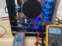
I used 3K3 in R7/8 and 5.1 in Z1/2. I'm unable to get the bias past ~.420V and I'm wondering if increasing Z1/2 to 6.2V (or higher) is the correct next step.
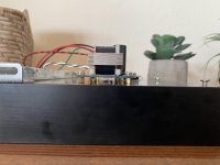
Attached is a picture of my setup in it's current state. The DMM on the right is connected to R2 (.47) measuring the bias and the DMM on the left is connected to the speaker terminals measuring the offset.
The amp has been on with bias/offset set for around 4 hours, so it should be warmed up. Using an IR thermometer, the heatsink surrounding the F6 PCB is around 50-55 degrees celsius.
As always, thanks for your help.
IV
Attachments
I can't find the post but Zen Mod called out a 6V8 with the 3.3KOhm. I tried that first and everything worked so don't know if the 6V2 will get you close enough.
yes! this one (for those that look at 10 posts per page): https://www.diyaudio.com/forums/pass-labs/277850-f6-illustrated-build-guide-3.html#post4450227
Is it post 27?
yes! this one (for those that look at 10 posts per page): https://www.diyaudio.com/forums/pass-labs/277850-f6-illustrated-build-guide-3.html#post4450227
Thanks for the quick reply. I saw post 27 but wanted to double check prior to desoldering and ordering 6v8. I have the 6v2 on hand and if those will work it would save me from ordering; however, Id prefer not to have to desolder the 6v2 if they won’t bias properly either.
Regardless, appreciate the help.
Hello, 6.2 V and 3.3 kΩ works fine for me and bios value reaches 500 mV.
Edwin,
I agree with others here, you should be able to get to the optimum bias of 500mV, 6.2V or 6.8V should work.
Also double check you have the correct valued pots soldered.
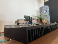
And finally, when zooming in on your pic, it seems that many of the small resistors have been soldered in the 'daddy long legs' style (perhaps this was done for easy debugging). I would recommend trimming them down to be flush with the board, with the exception of the large power resistors of course. The circuit works fine with these "high riding" resistors but it needlessly increases lead inductance which with some circuits affects the performance.
With large power resistors, I have nuts of various sizes that I place under the power resistor prior to soldering. I then "eyeball" it so that there is enough airflow around the resistor. I remove the nut with a tweezer or nudge it with the pencil after soldering and it always comes out perfect. You can also use a cut up pencil to approximate the height - works well.
Best,
Anand.
I agree with others here, you should be able to get to the optimum bias of 500mV, 6.2V or 6.8V should work.
Also double check you have the correct valued pots soldered.
And finally, when zooming in on your pic, it seems that many of the small resistors have been soldered in the 'daddy long legs' style (perhaps this was done for easy debugging). I would recommend trimming them down to be flush with the board, with the exception of the large power resistors of course. The circuit works fine with these "high riding" resistors but it needlessly increases lead inductance which with some circuits affects the performance.
With large power resistors, I have nuts of various sizes that I place under the power resistor prior to soldering. I then "eyeball" it so that there is enough airflow around the resistor. I remove the nut with a tweezer or nudge it with the pencil after soldering and it always comes out perfect. You can also use a cut up pencil to approximate the height - works well.
Best,
Anand.
Last edited:
Edwin,
I agree with others here, you should be able to get to the optimum bias of 500mV, 6.2V or 6.8V should work.
Also double check you have the correct valued pots soldered.
And finally, when zooming in on your pic, it seems that many of the small resistors have been soldered in the 'daddy long legs' style (perhaps this was done for easy debugging). I would recommend trimming them down to be flush with the board, with the exception of the large power resistors of course. The circuit works fine with these "high riding" resistors but it needlessly increases lead inductance which with some circuits affects the performance.
With large power resistors, I have nuts of various sizes that I place under the power resistor prior to soldering. I then "eyeball" it so that there is enough airflow around the resistor. I remove the nut with a tweezer or nudge it with the pencil after soldering and it always comes out perfect. You can also use a cut up pencil to approximate the height - works well.
Best,
Anand.
Hello, 6.2 V and 3.3 kΩ works fine for me and bios value reaches 500 mV.
I can't find the post but Zen Mod called out a 6V8 with the 3.3KOhm. I tried that first and everything worked so don't know if the 6V2 will get you close enough.
Is it post 27?
yes! this one (for those that look at 10 posts per page): https://www.diyaudio.com/forums/pass-labs/277850-f6-illustrated-build-guide-3.html#post4450227
Got the bias and offset to work with 6V2 in Z1/Z2! I ordered the 6V8 just in case, but thought I would give the 6V2 a try.
@Anand,
The "daddy long legs" style was indeed a result of debugging. Now that I have a desoldering tool to fix my (many) mistakes, I may try to trim the smaller resistors down. The suggestion of putting nuts down or purchasing some forming pliers similar to what @Claas recommended are great ideas as well.
Thanks again for all the help/guidance. Hopefully I'll get to test the amp with some speakers between now and the end of the weekend.
Attachments
I'd suggest leaving the resistors as they are - compared with the long tracks on this pcb, the extra leg lengths are insignificant - maybe not as neat as 'apple pie' but working okay for now.
Hi all,
Finally got done moving and had an opportunity to get back to the build. I purchased some nichicon capacitors (c1,2) from mouser and noticed they’re much larger than the ones included in the f6 parts kit from diyaudiostore. Any issue with the nichicon capacitors other than size? See attached image for comparison. Both capacitors are 1,000uf 25v.
P/N: 493-14501-NDi
Thanks!
Bigger has longevity advantages but they cost more.. as the reason you were supplied bitty ones.
Small to No need for a soft start in an F6.
Bigger has longevity advantages but they cost more.. as the reason you were supplied bitty ones.
Small to No need for a soft start in an F6.
@Bare,
Makes sense. I have plenty of room, which could've been a problem if I was tight on space.
Also, yes I also read that the soft start is unnecessary on the F6. I installed it just to tinker with the build, while I was waiting for other parts to come in.
Is leaving it in going to degrade the system, or is it simply redundant/unnecessary?
I have experienced the occasional blown fuse with no soft-start but my configuration is a bit unique. I've got them configured as monoblocks with a 220VA Hammond feeding a 120k uF capacitor bank powering one F6 channel per chassis.
I switched from a 2.5A to a 3.0A slo-blo and it seems to hold. Somewhere in here, I need to install the soft-start and see if the 2.5A will work. More logically, I should be looking at a 1.5A slo-blo as the monoblocks should be only using half the current at steady state as the stereo version does.
I switched from a 2.5A to a 3.0A slo-blo and it seems to hold. Somewhere in here, I need to install the soft-start and see if the 2.5A will work. More logically, I should be looking at a 1.5A slo-blo as the monoblocks should be only using half the current at steady state as the stereo version does.
The fuse size is usually based on the VA rating of the power transformer. With a large amount of power supply capacitance, the peak current draw is usually at power turn-on when the large capacitors draw the maximum current that the transformer can supply. Most diyers size transformers for Class A amplifiers to supply more current than the steady state demand of the amplifier, typically two times or more.
So a starting size for a slow blow fuse would be transformer VA divided by powerline VAC. Increase fuse rating if the fuse blows.
Thermistors in series with the transformer primary windings will reduce the current flow.
So a starting size for a slow blow fuse would be transformer VA divided by powerline VAC. Increase fuse rating if the fuse blows.
Thermistors in series with the transformer primary windings will reduce the current flow.
Hi everyone,
I'm in the process of setting the bias and offset and am having trouble with the offset on Channel B. No issues with Channel A (Bias = .500V / Offset = 0V). I'm able to bias channel B to .500 without issue; however, I can't get the offset to to move above -20V turning P1.
In an effort to diagnose/fix the problem, I've completely replaced R1-R13, P1 and increased Z1/Z2 to 6V8. R7/R8 are 3K3 and R9/R10 10K. Also, I've checked that Q3/Q4 are the correct values.
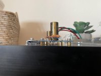
I'm using split washers on top of the large flat washer, to ensure Q1/Q2 are nice and snug.
None of these steps have worked. Turning the screw on P1 does nothing to the offset value. The only thing that seems to affect the offset is increasing the bias. I briefly increased the bias above 1V and the offset increased to ~-10V.
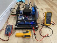
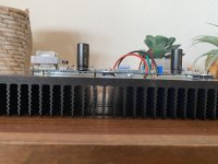
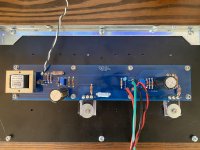
My next idea was to replace Q1/Q2, but I thought I would first check with the community to see if I'm missing something. Below are some pics to show the current state (Ignore the absence of a zip tie around Q3/Q4, as I haven't replaced the one I cutoff last night to confirm values).
Also, just to confirm, P1/P2 and Z1/Z2 face the same direction on channel B, correct? I noticed this was different on channel A, where they're installed in opposite directions from one another. Not sure if that would affect the offset if they were installed backwards, but it was just an observation that I made and want to confirm with the group.
Appreciate the help/hand holding.
I'm in the process of setting the bias and offset and am having trouble with the offset on Channel B. No issues with Channel A (Bias = .500V / Offset = 0V). I'm able to bias channel B to .500 without issue; however, I can't get the offset to to move above -20V turning P1.
In an effort to diagnose/fix the problem, I've completely replaced R1-R13, P1 and increased Z1/Z2 to 6V8. R7/R8 are 3K3 and R9/R10 10K. Also, I've checked that Q3/Q4 are the correct values.
I'm using split washers on top of the large flat washer, to ensure Q1/Q2 are nice and snug.
None of these steps have worked. Turning the screw on P1 does nothing to the offset value. The only thing that seems to affect the offset is increasing the bias. I briefly increased the bias above 1V and the offset increased to ~-10V.
My next idea was to replace Q1/Q2, but I thought I would first check with the community to see if I'm missing something. Below are some pics to show the current state (Ignore the absence of a zip tie around Q3/Q4, as I haven't replaced the one I cutoff last night to confirm values).
Also, just to confirm, P1/P2 and Z1/Z2 face the same direction on channel B, correct? I noticed this was different on channel A, where they're installed in opposite directions from one another. Not sure if that would affect the offset if they were installed backwards, but it was just an observation that I made and want to confirm with the group.
Appreciate the help/hand holding.
Attachments
-
 2A98266A-F73E-4732-95BB-8A74FD0A9B01.jpg660.7 KB · Views: 201
 -
 22A15CCC-421E-4888-9C53-23C2AE7398BC.jpg859.9 KB · Views: 219
 -
 8488A8D8-C1D9-4DA1-B68D-78B53D9A93D0.jpg774.3 KB · Views: 207
 -
 CF6AD779-4DCD-4DC5-9914-D61207D79F17.jpg825.3 KB · Views: 209
 -
 FAA6C3A8-6D49-428D-B501-CCCF399C7776.jpg986 KB · Views: 131
Did you ohm out your transformer secondaries? They are part of the bias and offset circuits. Lift one leg of R11 and R12 and check. Each winding should be about 28 ohms.
- Home
- Amplifiers
- Pass Labs
- F6 Illustrated Build Guide