JT,
Here's the link:
https://www.diyaudio.com/forums/pass-labs/277850-f6-illustrated-build-guide.html#post4406647
Check what Jim says about R11, R12.
Here's the link:
https://www.diyaudio.com/forums/pass-labs/277850-f6-illustrated-build-guide.html#post4406647
Check what Jim says about R11, R12.
JT,
From the 3rd post of this thread which has a revised BOM:
Best,
Anand.
From the 3rd post of this thread which has a revised BOM:
R11,12 110ohm (The gatestopper resistor can be anywhere from 47ohm to 680ohm, this helps protect from ultrasonic oscillation. I used 110ohm in mine as I’ve learned from experience, that a bit more than 47ohm seems to work better.)
Best,
Anand.
This might seem a bit "nuts" to many people but the type of resistor in this position seems to significantly effect the overall sound of the amp - I have a preference for those Manganin resistors from "General Resistor Co" (UK) called 8G16 - not cheap things but a more detailed, somewhat softer sound, unlike the "naked vishays"
R5 inlet resistor is also another place to try options, IMO naturally.
R5 inlet resistor is also another place to try options, IMO naturally.
Hi all,
I have now changed my zenors and R7 + R8. Both channels biased and offset to a couple of mV.
I swapped out my ACA for the F6 on the B1 Nutube and I have sounds...all of one channel and what sounds like about 10% of the other. The good channel souds sweet, very quiet and no hum.
I have reflowed all joints and the only difference I can pick out is that the Q1 on the quiet channel is 10 °C warmer than the other IRFP240's. After a couple of minutes it is 43°C rather than 33°C measured on the others.
My electronics knowledge is growing and I got lucky with the previous two kits but this has me stumped. Could someone please point me in the right direction?
point us to your ref. schmtc
what are values of source resistors (mosfets)
thermal pads?
torque of mosfet screws?
check continuity of xformer windings (primary)
R3,R4 values?
all resistors in proper positions?
what are values of source resistors (mosfets)
thermal pads?
torque of mosfet screws?
check continuity of xformer windings (primary)
R3,R4 values?
all resistors in proper positions?
Overunity,
As ZM has said above, but also make sure that the back of Q1 is not accidentally shorted to ground. The back of Q1 (and Q2) is also connected to the "drain". If your thermal pad is slightly ripped, then the drain will have continuity with ground, and then Q1 MOSFET will start to conduct current/short to ground which is wrong.
The easiest way to check is to make sure that the 3 pins on Q1 and Q2 do not have continuity with ground. Also check your thermal pads. I stick with Aluminum Oxide insulators since it's really hard to break/crack them.
Also make sure R1 is 0.56 ohms and R2 is 0.47 ohms. They can both be 0.47 ohms actually but 0.56 ohms slightly changes the second harmonic character of the amp for better sonics.
R3 should be 100 ohms, R4 should be 18 ohms.
You do have +/- 22 to 26V supplies right?
This is an extremely simple circuit, it shouldn't be too hard to figure out what is wrong.
Best,
Anand.
Zen Mod,
Thanks for the assistance. Build is as the design in the first post of this thread. I have only changed Z1 and Z2 to 5.6V and R7 and R8 to 3k3 to enable bias etc.
Keratherm pads, torque is roughly the same on both channels.
R3 100R 3W R4 18R
I have not checked primary windings, I shall do that tomorrow. I guess removal from PCB is best?
I had thought the issue may lie closer to input as I had checked voltages on mosfets and all compared to opposite channel.
I checked each component with DMM prior to fitting but I will double check positions.
Thanks
no need to remove xformer, check it in situ
pinout (numbers) is in sch
compare with good channel
secondaries are good, or you couldn't get biasing of mosfet(s)
also compare voltages across source resistors ; suspicion on lower mosfet drain short to gnd
pinout (numbers) is in sch
compare with good channel
secondaries are good, or you couldn't get biasing of mosfet(s)
also compare voltages across source resistors ; suspicion on lower mosfet drain short to gnd
Last edited:
Thanks for the pointers guys, ZM had it in the first list and I should have found it...resistors not in the correct place.
I checked resistances around the input and noticed a difference between the input and ground on the faulty channel. I lifted one end of R5 and R6 to check true R and found R6 to be 47R not 47K! I knew I had started with the correct parts so I lifted R11 and R12 and the 47K was in R11. Checked bias and temps again and Q1 is still a little warmer so I will dismantle and inspect the heatsink surface and thermal pad.
So, I am now a little more confident with fault finding and finding my way around schematics and PCBs.
Thanks to all who have the skills to help others and develop the mods, I will be ordering parts to try some mods as soon as I have appreciated the original for what it is.
Big thanks to Mr. Pass for the gift of the designs and his time and passion for these matters.
I have had a quick listen and it has so much more bass than the ACA, it can be run in for a few hours tomorrow before I judge.
Awesome O and good on your for sharing the mistake, if you had not it's not a teaching moment it says something about you. Thanks...
BTW, I have done the same more than once. 🙂
JT
BTW, I have done the same more than once. 🙂
JT
Hi,
I'm looking for an F6 LTspice model; I can't find it with search. Nor with help of mrGoogle.
Hope someone can help.. albert
I'm looking for an F6 LTspice model; I can't find it with search. Nor with help of mrGoogle.
Hope someone can help.. albert
Awesome O and good on your for sharing the mistake, if you had not it's not a teaching moment it says something about you. Thanks...
BTW, I have done the same more than once. 🙂
JT
+1.
Thanks for sharing Overunity.
Best,
Anand.
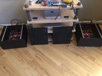
Finally! After a few missteps with the buffer JFETs, got my F6 monoblocks up and running. Next up is upping the game for some monsterblocks but until the next pair of transformers show up, enjoying these things for awhile.
The bass! Oh. Em. Gee. The bass!
I have Peter Gabriel's "The Last Temptation of Christ" breaking things in because "It is Accomplished!"
-tom
The bass! Oh. Em. Gee. The bass!
I have Peter Gabriel's "The Last Temptation of Christ" breaking things in because "It is Accomplished!"
-tom
Attachments
Last edited:
C1,2 Replacement
Hi all,
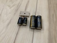
Finally got done moving and had an opportunity to get back to the build. I purchased some nichicon capacitors (c1,2) from mouser and noticed they’re much larger than the ones included in the f6 parts kit from diyaudiostore. Any issue with the nichicon capacitors other than size? See attached image for comparison. Both capacitors are 1,000uf 25v.
P/N: 493-14501-NDi
Thanks!
Hi all,
Finally got done moving and had an opportunity to get back to the build. I purchased some nichicon capacitors (c1,2) from mouser and noticed they’re much larger than the ones included in the f6 parts kit from diyaudiostore. Any issue with the nichicon capacitors other than size? See attached image for comparison. Both capacitors are 1,000uf 25v.
P/N: 493-14501-NDi
Thanks!
Attachments
- Home
- Amplifiers
- Pass Labs
- F6 Illustrated Build Guide