How are folks measuring the temperatures on the heatsink? What tool and what protocol, more exactly?
Etekcity Infrared Thermometer 774
Thanks!
I should be finally ready to bias up this coming weekend. Don't want to kill anything due to stupidity. Do I measure on the heatsink at the FET?
If anything, I'll just bias to the value 6L6 gives in the 1st post but I know I'm going to want to experiment once the amps are running correctly.
Measure everything looking for the hottest spots. Look for consistency at each FET. If not make sure torque is same.
Measure everything looking for the hottest spots. Look for consistency at each FET. If not make sure torque is same.
awesome and thanks for the quick replies!
-tom
I bought some these to try out….worked well.
Electronic Thermostat Controller, DROK DC 6-30V 24V Digital Temperature Control Board.
Used a 9v battery…put in a small case.
Electronic Thermostat Controller, DROK DC 6-30V 24V Digital Temperature Control Board.
Used a 9v battery…put in a small case.
How are folks measuring the temperatures on the heatsink? What tool and what protocol, more exactly?
diyAudio member Mark Johnson makes his recommendation here:
https://www.diyaudio.com/forums/pass-labs/370689-diy-sony-vfet-builders-thread-165.html#post6716632
https://www.diyaudio.com/forums/pass-labs/370689-diy-sony-vfet-builders-thread-168.html#post6718832
Multimeter Uni-T UT123 is delivered with a temperature probe. A small second meter is also useful when travelling or when the first one is used to measure current.
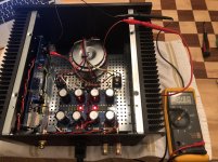
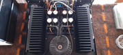
The journey continues. Power up and biasing the left channel seemed to go well. Let the monsterblock sit for over an hour and checked the bias and offset multiple times. Got the voltage across R2 to sit at 0.501VDC per 6L6's build guide. As I didn't have a thermometer, I relied on the hand test per Mr. Nelson. The heatsink never got uncomfortable to touch no matter how long it sat on. Then I hooked it up to a speaker. Got some odd squeaks and squawks so decided to power it down. Then I noticed the V- led hanging on for awhile compared to the signal board and V+ leds that died quickly. Taking a break for a few, maybe work on the other channel chassis. I need to rebuild the energy so I can check everything over as I feel I didn't do as good a job paying attention to detail during soldering as I normally do. something seemed amiss. Maybe it isn't but definitely seemed like it at 3am.
Attachments
It's all those red LEDs. Blue is more soothing 😎 (just kidding)
My personal experience was that 550mV was the point at which my F6 started to sound good. Below that, it just did not sound "right". Above 575mV I could not hear any improvement. More bias just increased the heat sink temps.
My personal experience was that 550mV was the point at which my F6 started to sound good. Below that, it just did not sound "right". Above 575mV I could not hear any improvement. More bias just increased the heat sink temps.
It's all those red LEDs. Blue is more soothing 😎 (just kidding)
My personal experience was that 550mV was the point at which my F6 started to sound good. Below that, it just did not sound "right". Above 575mV I could not hear any improvement. More bias just increased the heat sink temps.
Thanks for the words of advice. And the giggle. I needed the giggle. Speaking of giggles, for giggles, I tried the amp this morning, to see if the bias would still hold. R7 (the zener feeder) is smoking. I tried the 3k ones with the 6V8 zener that Zen Mod suggested. Looks like I did something wrong. Luckily I have the stock kit resistors and zeners to try as opposed to waiting for another Mouser/DigiKey shipment. Regardless, time to trouble shoot before I fry another resistor or two. Before that, fresh air and sunshine!
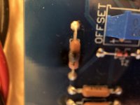
I zeroed it out last night but didn't test it when I fired it back up in the morning so I'm unsure where it was at the time of the fry. Need to order replacement resistors then going to check all the components I can and reflow the board.
Good day friends. I am building an F6 amplifier with the DIY Audio blue boards.
The problem I am having is that the bias voltage across 0.47R resistors only come up to 245mV.
Is there something I must know about? The PSU supply rails are spot on at 24vdc +/- and ample current. All components are top end and test correct.
The amplifier also plays and sounds good... but the bias is low.
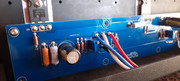
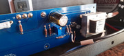
Wow... just wow... I found a boo-boo but unsure if it is related to R4 burning out. Guessing there is a good chance but I'm new to transistors. I installed both 2SK170s onto the B channel board and (thus!) both 2SJ74s on the A channel. Luckily, I only powered up B channel.
I don't know how to test the 2SK170s or if I need to. Do I need to buy all new JFETs? Any advice?
I don't know how to test the 2SK170s or if I need to. Do I need to buy all new JFETs? Any advice?
Attachments

which one is your exact ref. sch and give us details about biasing parts of circuit
They were built as per this post.

- Home
- Amplifiers
- Pass Labs
- F6 Illustrated Build Guide