Um, there's a 62.5R/m wire from German manufacturers "Block RD" on the Conrad Electronic website (part no 422420) - don't know if it's Isotan or Manganin (0.1mm dia) or what but worth a look.
Some of the eBay people aren't too good with queries but try sending a follow-up - I found "lci-electronics" in Bulgaria to be good guys, but not sure what's available.
"evek.de" in Germany still make insulated Mn wire for the marketplace - I didn't know Harris still supplied insulated Mn wire on the eBay, but not cheap. I think there's also a company in Wales (UK) that sells this product by the metre but a hefty surcharge.
Finally... I'm done
Hi guys,
it's been a while since my struggles with my F6 and your great help.
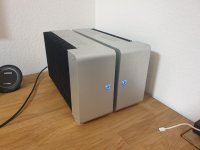
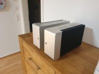
Just wanted to show you my final results.
I'm very very happy with my F6 and the outcome of my chassis.
Only thing that's a bit sad.... the guy who did the anodizing of my covers messed it up.
Thank you all very much 🙂
Hi guys,
it's been a while since my struggles with my F6 and your great help.
Just wanted to show you my final results.
I'm very very happy with my F6 and the outcome of my chassis.
Only thing that's a bit sad.... the guy who did the anodizing of my covers messed it up.
Thank you all very much 🙂
Attachments


Thank you very much 🙂
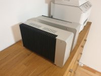
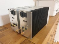
It was a pain in th a** to make them.
Everything is hand made.
I don't have a milling machine....
It was a pain in th a** to make them.
Everything is hand made.
I don't have a milling machine....
Thank you all very much 🙂
Great that you like it too.
@ 2 picoDumb
Never heard that phrase before 😀 Had to google a bit.
Great that you like it too.
@ 2 picoDumb
Never heard that phrase before 😀 Had to google a bit.
F6 Hum
I have been asked to take a look at this F6 built by a third party. All the PCBs are from DIYaudio store along with the jfets and mosfets. The Transformer is a Zero 500VA 18-0-18 with various other secondaries for the Soft Start and and speaker protection. The Wiring (including the Chassis and PSU grounding) is as per spec. I have incorporated the 3k3/LED mod to enable the bias to be set at the spec 0.5mV the offset is less than 10mV steady state and warms up as it should. I couldn't get this before with the 5.1v zener.
Al the components look genuine items and purchased via Mouser/RS and or Farnell I believe.
Buggered if I can find the hum issue (not vol dependant) The hum rises as the amp board 1000uF cap charges and we get output.
I have now separated the AC (top left) from the DC. Initially they were all tie wrapped together in a loom. The Hum is better by some margin now by doing this.
I have built many F6's and other Pass First Watt clones without this issue.
Any help appreciated.
TIA
Last edited:
Yep.
Maybe the easiest solution is to magnetically shield the Jensen and if possible also put the power transformer in some kind of can.
Maybe the easiest solution is to magnetically shield the Jensen and if possible also put the power transformer in some kind of can.
Donut is too close to input Iron
Yup, completely agree. Start by removing both boards and do what I did. Take them OUTSIDE of the chassis.
MY VFET CSX1 uses the same input transformer and I solved the hum noise problem by building a separate power supply chassis.
… and the diodes directly opposite the transformer doesn't help either
I doubt that you can do it but if you (re)moved that front meter (or maybe change it) and stand the transformer vertically (with a bracket), then move the rectifiers and caps forward, away from the signal transformer (ZM), this might be enough - or add the transformer shielding as suggested (pico) - this might save you adding a separate case.
I don't think you could mount the rectifier board on top of the transformer but worth a try
Also, suggest you twist the wires, as AndrewT used to emphasize, and shorten them where possible.
Many thanks guys for the confirmation of the hum issue, plan B comes into action. 'Distance' and some good ol 'twisting'...
F6 hum very persistent....
So I moved the TX and psu well outside the case and placed some shielding on the little 'in' tx.


Sadly no improvement...still hummming away. eerrrrrr.
So I moved the TX and psu well outside the case and placed some shielding on the little 'in' tx.
Sadly no improvement...still hummming away. eerrrrrr.
Last edited:
it still must be wired correctly
pull those spaghetti out and wire it as you did with previous ones
pull those spaghetti out and wire it as you did with previous ones
Hello, this is my first post here.
Inspired by the F6 Illustrated Build Guide from 6L6, I ventured into this project.
Only the power supply board I used is different.
At the output of the board, measured between + and -, there are 50 V DC on each side.
Measured between + and gnd it is 25 V DC.
Measured between - and gnd, it is also 25 V DC.
In the diyAudio Power Supply Circuit Board v3 illustrated build guide I read that this is ok.
My question about my safety:
Can I now connect the F-6 amplifier board to the supply board and start setting BIAS and OFFSET as described in 6L6?
I would appreciate an answer very much.
greeting
Dieter
- Home
- Amplifiers
- Pass Labs
- F6 Illustrated Build Guide