if it did, your preamp wouldn't have been blown and all the other circuits should not have blown. i dare think what would have happened if you had touched the chassis at the time.
The chassis is earthed. So the chassis is safe.
The rca/speaker sockets may have posed a danger though.
Can't really understand what happened. The mains wires are going directly to the transformer. This is the only mains connection inside the amp. The only thing I can think of is the connection of a mains wire in the plug to the earth wire, and find a way trough the cl60 to audio ground, and then via the rca connection to the preamp. And the preamp earthed via another mains plug?
Can't really understand what happened. The mains wires are going directly to the transformer. This is the only mains connection inside the amp. The only thing I can think of is the connection of a mains wire in the plug to the earth wire, and find a way trough the cl60 to audio ground, and then via the rca connection to the preamp. And the preamp earthed via another mains plug?
Taking photos would probably help us help you, otherwise rebuild the amp.
It's most likely a cold soldered joint if it has worked for all this time and only failed now.
I'll be glad to take any photos requested.
The suggestions that there was a short at the receptacle are consistent with what I experienced (flash/arc at the plug). I have since replaced this receptacle and will be going through my house doing the same for the rest of those that have a loose fit.
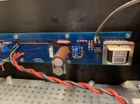
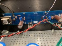
Earlier, you mentioned the PSU, so I've taken a photo of the bottom (and the nylon offsets I used).
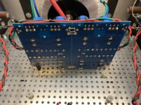
Also, here's a photo of the left side and the right side. On the left the lifted trace is obvious. The two jfets lost their zip tie and are now melted together. The right is not showing obvious signs of damage.
I've already started ordering parts. If the PSU and the transformers are OK, there's not really too much to buy. Should I just disconnect the board and test the PSU? (with ground to earth replaced)
Thanks
The suggestions that there was a short at the receptacle are consistent with what I experienced (flash/arc at the plug). I have since replaced this receptacle and will be going through my house doing the same for the rest of those that have a loose fit.
Earlier, you mentioned the PSU, so I've taken a photo of the bottom (and the nylon offsets I used).
Also, here's a photo of the left side and the right side. On the left the lifted trace is obvious. The two jfets lost their zip tie and are now melted together. The right is not showing obvious signs of damage.
I've already started ordering parts. If the PSU and the transformers are OK, there's not really too much to buy. Should I just disconnect the board and test the PSU? (with ground to earth replaced)
Thanks
Attachments
If you have a lab powersupply use that to power the board and see what components are still operating correctly.
I would probably just replace everything. The most expensive item is the transformer so just test those.
I would probably just replace everything. The most expensive item is the transformer so just test those.
question
That little blue disc capacitor between connector port 2 and 3 on the build guide pics, that is described on the first watt power supply diagram as a .0033 line cap.
Would that not actually be .0033uF? As in a ceramic safety cap. A big difference but I don't like to assume anything at my newbie level. 😕 Thanks,
Don
A ceramic safety cap is good:
https://www.mouser.com/ProductDetai...GAEpiMZZMve4/bfQkoj%2BBujwpW5wHzCuxF5C76Iqaw=
I believe an X2 rated film-type safety cap is also OK if you want to save 50 cents. Something like this (for 120V mains):
https://www.mouser.com/ProductDetail/667-ECQ-U2A332KL
re-using power supply at 30V
Hello all -- I'm planning to finally start my F6 build. I have the parts (except the MOS FETs which are backordered at Mouser and Digikey!).
But I do have questions regarding the power supply that I already have but which has 30V rails instead of the standard 25V (something similar came up in this thread before, but I don't quite get what the final answer is).
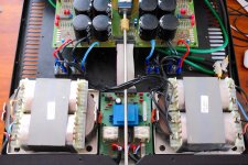
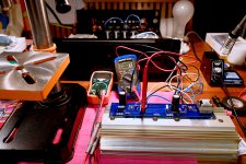
I was planning to re-use my existing massive power supply from an old Gryphon Tabu integrated (see picture). There are 2 monster C-core transformers, and I will throw out all the pre-amp parts to get sufficient space to make it a nice F6 build.
The original Gryphon schematic says 2x50V rails (dual mono), and my idea was to put the Tx primaries in series to halve the VAC, should make about 25V DC, perfect for my F6 build? That was the idea, anyway.
Well, it turns out that the secondary is more like 22VAC and the resulting rails are at ~30V.
I have 2 questions:
1) is it safe, long-term, to run these transformers at 120V in the 230V configuration, in order to half the output VAC, or will I get into problems? Does it just mean I can't get to the full VA spec? I don't know what these guys are capable of delivering anyway, but the old amp was spec'ed at Class AB, 2x100W RMS at 8 Ohm, 200W at 4 Ohm, and 300W at 2Ohm -- shouldn't I be just fine using these for a 25Watt class A?
Or am I missing something? Are there any other issues with running transformers at half the expected primary voltage?
2) Is there a problem with running the F6 rails at 30V, as long as I keep the bias at 25W, the same value as for 25V? I made sure the Caps can stand 30V, are there any other concerns?
There were discussions on this before. But the answers were mostly about changing the MOS FETs to something bigger, better (but the IRFP240 are spec'ed at 200V anyway, so what's the problem?), and about evenutal cooling issues when you go to higher power -- but I'll be very happy with 25 Watt into 8 Ohm, that will be more then enough for my Zu speakers.
Shouldn't I be able to run at 30V and 25Watt just fine?
Any reply, suggestion, insight is much welcome before I just go ahead and try it out... 🙂
Thanks, LatB
Hello all -- I'm planning to finally start my F6 build. I have the parts (except the MOS FETs which are backordered at Mouser and Digikey!).
But I do have questions regarding the power supply that I already have but which has 30V rails instead of the standard 25V (something similar came up in this thread before, but I don't quite get what the final answer is).
I was planning to re-use my existing massive power supply from an old Gryphon Tabu integrated (see picture). There are 2 monster C-core transformers, and I will throw out all the pre-amp parts to get sufficient space to make it a nice F6 build.
The original Gryphon schematic says 2x50V rails (dual mono), and my idea was to put the Tx primaries in series to halve the VAC, should make about 25V DC, perfect for my F6 build? That was the idea, anyway.
Well, it turns out that the secondary is more like 22VAC and the resulting rails are at ~30V.
I have 2 questions:
1) is it safe, long-term, to run these transformers at 120V in the 230V configuration, in order to half the output VAC, or will I get into problems? Does it just mean I can't get to the full VA spec? I don't know what these guys are capable of delivering anyway, but the old amp was spec'ed at Class AB, 2x100W RMS at 8 Ohm, 200W at 4 Ohm, and 300W at 2Ohm -- shouldn't I be just fine using these for a 25Watt class A?
Or am I missing something? Are there any other issues with running transformers at half the expected primary voltage?
2) Is there a problem with running the F6 rails at 30V, as long as I keep the bias at 25W, the same value as for 25V? I made sure the Caps can stand 30V, are there any other concerns?
There were discussions on this before. But the answers were mostly about changing the MOS FETs to something bigger, better (but the IRFP240 are spec'ed at 200V anyway, so what's the problem?), and about evenutal cooling issues when you go to higher power -- but I'll be very happy with 25 Watt into 8 Ohm, that will be more then enough for my Zu speakers.
Shouldn't I be able to run at 30V and 25Watt just fine?
Any reply, suggestion, insight is much welcome before I just go ahead and try it out... 🙂
Thanks, LatB
Attachments
Please note that 30V rails means running the jfets at higher voltage than their rating.
Mr. Pass has indicated that the Toshiba jfets are conservatively rated so that voltage
should be ok. (See F5 turbo article, for example.) However, dissipation could be an
issue so you should use low-ish Idss jfets (say 7mA) and also
consider putting small TO92 heatsinks on them.
Mr. Pass has indicated that the Toshiba jfets are conservatively rated so that voltage
should be ok. (See F5 turbo article, for example.) However, dissipation could be an
issue so you should use low-ish Idss jfets (say 7mA) and also
consider putting small TO92 heatsinks on them.
Please note that 30V rails means running the jfets at higher voltage than their rating.
Mr. Pass has indicated that the Toshiba jfets are conservatively rated so that voltage
should be ok. (See F5 turbo article, for example.) However, dissipation could be an
issue so you should use low-ish Idss jfets (say 7mA) and also
consider putting small TO92 heatsinks on them.
Thank you, I had not thought about that! But I'm assuming I'll be fine on the MOSFET side of things?
I listened to Nelson Pass' Burning Amp 2012 talk again. Maybe I should consider to put in degeneration resistors, as he proposes to address the power problem.
However, in his talk he had 10R degeneration resistors (also the M2X Ichikawa input stage has 10R resistors). So I wonder how this makes any difference?
For an Idss of, say, 7mA, which for rails of 30V corresponds to a resistance across the JFET of ~4.3 KOhm -- how can a 10R resistor in series make any difference?
So I don't quite understand Mr. Pass' statement that introducing these resistors would help with bringing the power dissipation down for the JFETs -- what am I missing?
Given that the LSJ74 has max VGDS of only 25V (40V for the LSK170, so that's good) I am considering the Cap multiplier that @2 picoDumbs proposed earlier.
Before I go there, with the complication of having to sink another 5 Watt per channel for the additional MOSFET, I want to be sure I can actually use these transformers in their 230V configuration at only 120V -- will this be a problem?
Thanks again for any help and advice with this!
😀 There is always Ettore Bugatti's famous quote / response to an owner who was complaining about his particular Bugatti :
Sell it on to someone who can afford it.
Sell it on to someone who can afford it.

LATB, running the transformers with the primaries in series will be completely fine. It’s designed for both series and parallel. The transformer only knows ratios, and is a perfectly good way to use them.
I already got a JFET buffer stage, do I need another one?
Thanks a lot for the info, that is reassuring!
I got delayed with drilling and tapping my heat sinks, hope to have at least the first channel going this weekend.
I'm still wondering about driving the input JFETs with +-30V rails. Which brings me to another question, if I may:
I recently finished the Mez B1 buffer (which, BTW, sounds great!). So I already have a JFET buffer stage that directly goes into the F6.
So I am wondering, why can't I just omit the JFET input buffer of the F6 all together and directly go from the B1 output on to the transformer primaries?? Certainly less parts there! Has anyone tried that successfully?
And finally, if I don't do that, and I keep the input buffer, couldn't I run the JFETs off the +- 10V from the Mez? Is +-10V enough for the input stage, or would that not be enough voltage sweep?
Just some ideas, and your input is much appreciated!
Thanks, LATB
LATB, running the transformers with the primaries in series will be completely fine. It’s designed for both series and parallel. The transformer only knows ratios, and is a perfectly good way to use them.
Thanks a lot for the info, that is reassuring!
I got delayed with drilling and tapping my heat sinks, hope to have at least the first channel going this weekend.
I'm still wondering about driving the input JFETs with +-30V rails. Which brings me to another question, if I may:
I recently finished the Mez B1 buffer (which, BTW, sounds great!). So I already have a JFET buffer stage that directly goes into the F6.
So I am wondering, why can't I just omit the JFET input buffer of the F6 all together and directly go from the B1 output on to the transformer primaries?? Certainly less parts there! Has anyone tried that successfully?
And finally, if I don't do that, and I keep the input buffer, couldn't I run the JFETs off the +- 10V from the Mez? Is +-10V enough for the input stage, or would that not be enough voltage sweep?
Just some ideas, and your input is much appreciated!
Thanks, LATB
Attachments
The F6 Unbuffered is a valid configuration, covered in the original article presented at BA 2012. The Mezmerize B1 should be able to drive that just fine, as long as the output resistance is kept fairly low.
- Home
- Amplifiers
- Pass Labs
- F6 Illustrated Build Guide