Hi 6c4c , thanks for your thought 😉
i will make some more testing , with higher Rsens value , knowing now how it works .
regarding the F7 , the only way to know how it really works is to have one on hand 😉
.
i will make some more testing , with higher Rsens value , knowing now how it works .
regarding the F7 , the only way to know how it really works is to have one on hand 😉
.
Hi Juma , thanks for you help 😉
what i understand is the sum of the tensions is always 10 v , but what's the link with damping factor ?
i have electric knowledge but not electronics , i wish i had some !!!
.
what i understand is the sum of the tensions is always 10 v , but what's the link with damping factor ?
i have electric knowledge but not electronics , i wish i had some !!!
.
Voltage on load falling with load's resistance is not just because of DF (1/Zout of the amp) but also due to voltage division with Rsense.
So you should measure the voltage from amp's output to ground, not just across the speaker.
So you should measure the voltage from amp's output to ground, not just across the speaker.
I have a question on the routing of the two, C1 & C2, 220uF capacitors.
I've seen some schematics that show the - ,negative pole, of C1 connected to the output and C2 connected to the negative power supply?
For instance this post in F6 with PCF, (also, elsewhere)
http://www.diyaudio.com/forums/pass-labs/288725-f6-pcf-2.html#post4676475
should the caps be connected that way or to the junction of the mosfet/SemiSouth sources and the resistors, R11 &R12?
The store PCB for the F6 have the caps - going to the mfet/resistor junction.
If it is connected as in the post above, what difference operationally/sonically does it make?
Also, I've noticed some recommend no source resistance or only on the bottom source and none on the top source, SemiSouth FETs, f.i. poster BUZZ.
C1 and C2 should be 1000uF caps as per 6L6's schematic posted earlier in this thread,the 220uF in the sim was me playing around with different values.Source resistance is as per 6L6 schematic if using irfp240's.I don't want to comment on what to use if you are using SemiSouth fets as I don't know.As for sonic differences with different C connections,sims show with connection as per schematic H3(3rd harmonic) is dominant which I find more in your face and bland.The other connection you mention(same as the sim) allows degeneration (AC wise I think) and sims show H2(2nd harmonic) dominant which I find more airy and wider sound .It is a matter of personal preference as our ears are all different although I've heard H2 dominance is preferred by a lot of people(that is what a lot of tube amps produce).
finished wiring up and everything but one blue led works sounds great biased at 5.1 and running at 115 degrees F(stole the kitchen meat thermometer in true DIY mode) I have the 6.8V zener so will raise my bias a bit but for now just good music!
I need custom version of F6 boards (for custom Diy Build), if someone able to create custom pcb's close enough to DiyAudioStore boards or original boards, PM please i can pay with PayPal.
Thanks
Thanks
strange, why not store boards?
Many reasons:
1) Some holes of my diyaudiostore boards destroyed dye expiriments with capacitors, resistors, recently i discovered that for my ears and my setup Nichicon FG sounds more pleasant than KZ, i don't care maybe they need burn-in time.
2) I do not want to apply any modfications to the chasis (enclosure).
3) I want that my build, looks completed.
Really i'am not need any big modfications to these PCBS, just need to remove 2 mount holes and move transistors plus decrease pcb size by using unused space. That's all.
So if someone want to earn some money, please PM

P.S Build not a commercial, i build amplifer for myself.
I got idea how to combine non-standart chasis and UMS, and want to share it with others

Idea is quite simply, get a part of aluminium list around 4mm thick, drill original case mount holes, then drill UMS holes over. Paint with black heat-resistant paint or anodize it. Then use thermal paste to make contact between chasis and aluminium list and screw pcb over 😀
Same idea can be used for other PCB's that you need to mount to your non-UMS chasis without applying any modfications to it
😉
Of course for not heat emitting PCB's like PSU, protection boards e.t.c, you can use thinner aluminium list around 1-2mm thicker.
Also i make picture explaination, so hope everyone understands it🙄
So where's my cookies now?! 😱
Last edited:
Finally Finished!
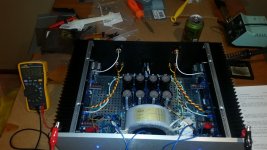
After starting a F6 one and a half years ago, I finally finished today. Power-up was uneventful and after a hour of warm-up I have it biased at 1.2 A per channel with less than a mV of DC offset.
Upon hooking up to my speakers, which have a sensitivity around 94 dB/W, all was silent. But, when I hooked up BOTH RCA inputs I got hum from both channels. If I remove one input the hum goes away. Changing sources from my CD player to tuner does not change the hum. The hum is present in both channels. The hum is not noticeable during playback, only during silence between tracks.
The input wiring is coax from the inputs to the board.
Any ideas where I should look?
Attachments
make better picture (right from top) or , even better , one like that and few more detailed ones
don't forget to post them here 🙂
don't forget to post them here 🙂
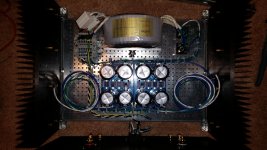
PSU Picture
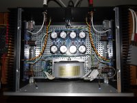
Here's the PSU. I wired the transformer with industrial terminal blocks. The green/yellow block is bonded to the case. The PSU 0V is tied to it via a thermistor. The static shield from the transformer (purple) is landed directly to ground. I have a ferrite on each of the primary windings.
The PSU measures +/- 24.3 VDC.
I'll work on getting a closeup pic of the input wiring, once I'm done listening to this track. Despite the hum during silence, this thing is amazing!😀
Attachments
Do you still get the hum if you disconnect the static shield?
Sent from my iPhone using Tapatalk
Sent from my iPhone using Tapatalk
You have a ground loop. That's why it's silent except when both RCA's are attached.
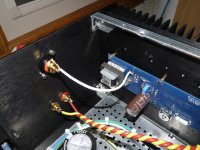
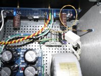
Looking at your photos the first thing I see is you have just one wire link between the 2 sides of the power supply PCB. There's holes for 6, use them all.
That, by itself, won't fix it, but it will help.
Next thing to try is attaching all the PSU grounds (Both PSU zero volt lines, both speaker negatives, and the CL-60 ground lift) into the same set of pads on the PSU. This should help the problem a lot. You have very nice looking wiring and it's a shame to cut into it, but you need to.
Do that and report back.
alvinlim: I lifted the static shield and found no change. I then landed it onto the thermistor lifted ground and found no change. The static shield is now back on the chassis ground.
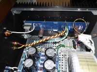
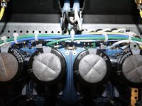
6L6 : I was worried about that. I've attached some more pictures of my PSU. Do you think it will be necessary to move the 0V lines (green) in by one pad, or do you think they will they be okay where they are. If I have to move them in, I'll save a spot for them, otherwise I'll just use the spot for another 0V jumper.
6L6 : I was worried about that. I've attached some more pictures of my PSU. Do you think it will be necessary to move the 0V lines (green) in by one pad, or do you think they will they be okay where they are. If I have to move them in, I'll save a spot for them, otherwise I'll just use the spot for another 0V jumper.
Attachments

- Home
- Amplifiers
- Pass Labs
- F6 Illustrated Build Guide