I am always erring around,
anyway I found these depletion mosfets:
At around 2 amps they need some Rs but then they are fine
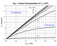
1) IXTH6N50D2 Stable with 1.1Ω, Ciss = 2.8nF; at 4.5S ; Stable (Example Rs 0.5Ω+0.56Ω; 1.2Ω//20Ω). Good tempco ... € 13/Mouser
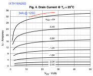
2) IXTH16N20D2. Ciss = 5,5nF Vgs = -2,2V @ 2Amp, 12S; Ron 80mΩ Take a Rs=1Ω or 1.2Ω €22/Mouser. Slight pos tempco, but with such a Rs that is moot.
The second looks like a powerhouse to me. The first one looks very useable too.
How to simulate these? Any models floating around? Any on-hand experience?
With these, it looks like the 'original' F6 with R100 looks like obtainable!
anyway I found these depletion mosfets:
At around 2 amps they need some Rs but then they are fine
1) IXTH6N50D2 Stable with 1.1Ω, Ciss = 2.8nF; at 4.5S ; Stable (Example Rs 0.5Ω+0.56Ω; 1.2Ω//20Ω). Good tempco ... € 13/Mouser
2) IXTH16N20D2. Ciss = 5,5nF Vgs = -2,2V @ 2Amp, 12S; Ron 80mΩ Take a Rs=1Ω or 1.2Ω €22/Mouser. Slight pos tempco, but with such a Rs that is moot.
The second looks like a powerhouse to me. The first one looks very useable too.
How to simulate these? Any models floating around? Any on-hand experience?
With these, it looks like the 'original' F6 with R100 looks like obtainable!
Attachments

how about this KISS?

the potmeter 5Ω allows skewing of the working points and hence the balance / phase of H2. which one I don't know yet;
once determined it should remain stable.
[I had such skewing on a balanced preamp in the nineties]
the potmeter 5Ω allows skewing of the working points and hence the balance / phase of H2. which one I don't know yet;
once determined it should remain stable.
[I had such skewing on a balanced preamp in the nineties]
what's the point of making an amp with OS parts so heavily degenerated?
OK, I'm biased, having extrastrong fetish for pure SQL OS, but anyway?
I'm just not seeing it - with all those compromises, none possible better than with good old IRFP
OK, I'm biased, having extrastrong fetish for pure SQL OS, but anyway?
I'm just not seeing it - with all those compromises, none possible better than with good old IRFP
I totally agree. all degeneration will destroy the vibration.
and putting a big .1 - 1F across it helps little probably.
note the F6/IRFP has 0.47Ω or 0.56Ω.
This beast has 1Ω. What is the difference?
here the degeneration is as variable as the sloppy drawing of a potmeter to its wiper the capacitor is attached.
top = little; bottom a lot (up to 1 or 1,5dB difference) - theoretically impossible to hear.
or have the other half use this; enfin you know the trick.
A bias V- would be more comfortable and is easy to make for the top. attach a green led (yes green please!?) to earth and the V- and presto you have some -1,7V bias for the wiper to scratch. Or a fixed-Voltage-device of 2.5V .
Then no degeneration on top.
But then you will have to test the harmonics of the whole with only degeneration at the bottom. . and that might switch the phase around (It is all in my head now, sorry)
and putting a big .1 - 1F across it helps little probably.
note the F6/IRFP has 0.47Ω or 0.56Ω.
This beast has 1Ω. What is the difference?
here the degeneration is as variable as the sloppy drawing of a potmeter to its wiper the capacitor is attached.
top = little; bottom a lot (up to 1 or 1,5dB difference) - theoretically impossible to hear.
or have the other half use this; enfin you know the trick.
A bias V- would be more comfortable and is easy to make for the top. attach a green led (yes green please!?) to earth and the V- and presto you have some -1,7V bias for the wiper to scratch.
Or a fixed-Voltage-device of 2.5V .Then no degeneration on top.
But then you will have to test the harmonics of the whole with only degeneration at the bottom. . and that might switch the phase around (It is all in my head now, sorry)
@triode_al
I understand the joy of experimenting with different devices however, in case you missed that post, Nelson said that his F6 test listeners preferred the MOSFET version over the JFET's.
https://www.diyaudio.com/community/threads/f6-amplifier.216616/page-285#post-3910852
I understand the joy of experimenting with different devices however, in case you missed that post, Nelson said that his F6 test listeners preferred the MOSFET version over the JFET's.
https://www.diyaudio.com/community/threads/f6-amplifier.216616/page-285#post-3910852
but I think his own preference was the Semisouth version and I believe he mentioned that somewhere
I think it was The Archivist (Dennis) from the OPLDF Dept of Records that told me 📚
thanks. Twitchie.
And now we are at it, I must say the Rs is not a source resistor at all, mostly with EUVL's potmeter, to some extent.
The Vgs derives from the transformer winding, and the top unit 'amplifies' by pushing current across that 0.47Ω (or 0.56Ω) and into the load of 8Ω; just like the bottom one (where the load is the output without a 0.47Ω resistor in between! And that 0.47Ω on the bottom is totally OUT OF THE LOOP.)
BOTH are a common-source amplifier; this is a balanced amplifier. Essentially 'equal'.
the TRICK is to make them just a bit unequal, imho statically, such that the 2nd harmonics can be changed. I call it skewing.
Because I had an amplifier where I could skew the DC points, and I observed the changes.
The French writer Héphaistos wrote about it in the magazine L'Audiophile. I did not understand what I did. I just did. Like so often.
As to that IXTH depletion device, it is much more like the IRFP than a power-JFET. So it is much ado about nothing.
But it does have great tempo; and can be run with say as low as 0.1Ω safely I assume. Looks like fun to me! No "Zenner's".
as I see it, you have both mosfets degenerated
simple as that
resistor can be "out of the loop" when looking at modulation (input side of part), but it is still heavily adding to intrinsic impedance of part ........ and that is important in context of output side of part
simple as that
resistor can be "out of the loop" when looking at modulation (input side of part), but it is still heavily adding to intrinsic impedance of part ........ and that is important in context of output side of part
- Home
- Amplifiers
- Pass Labs
- F6 Amplifier