poor 😎!
what will he do when his values are worse...?😀😀😀
Enjoy and stop measuring.


I built my second PC board today and tested it. The results look the same as my breadboard. The only significant differences between the 2 PC boards are the R100 output JFETs and the transformers. I doubt the JFETs are thatdifferent. I am thinking that during my breadboard testing I might have passed DC current through the transformer and saturated the core. I will attempt to "degauss" the transformer using the Jensen procedures. Here are the THD vs Frequency sweeps for the two PC boards. The first PCB (yesterday) on the left, and today's PCB on the right. Very different.
Attachments
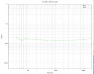

Periodic degaussing of nickle core transformers is a good idea. They really are gluttons for DC induced flux and will always do their best to incrementally saturate.
Bud
Bud
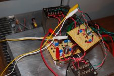
Hooked my F6 up with everything biased nicely and.......BZZZZZZZZ. 
Sounds like music is down the hall. Probably dont have time to debug. Who knows. Dont have the shield wire of transformer hooked up, but dont think its relevant. Could be haystack of construction. Been working on PCB anyway, so maybe get it etched and give her another go. Damnit. thought i would be first stereo listener. Oh well.
Sounds like music is down the hall. Probably dont have time to debug. Who knows. Dont have the shield wire of transformer hooked up, but dont think its relevant. Could be haystack of construction. Been working on PCB anyway, so maybe get it etched and give her another go. Damnit. thought i would be first stereo listener. Oh well.
Same as before. Not worried about it, just got to find the time to work on it. Give ya chance to mock later😀
Ill see what i can do. Threads been quiet and people need some good entertainment. Be back shortly.
Hooked my F6 up with everything biased nicely and.......BZZZZZZZZ.
Sounds like music is down the hall. Probably dont have time to debug. Who knows. Dont have the shield wire of transformer hooked up, but dont think its relevant. Could be haystack of construction. Been working on PCB anyway, so maybe get it etched and give her another go. Damnit. thought i would be first stereo listener. Oh well.
Buzzzz is usually a grounding issue. Is it a stereo amp? Disconnect one channel and see what you have. I would trouble shoot this before I worked on a PCB. You might find an error that you are duplicating on PCB.
You are the first to listen, is the Buzzzz of high resolution? Good imaging? 🙂
Rush
buzz
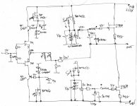
here is remainder for ya
not tested as is by Mighty ZM , but there is no reason for any doubts
few possible tweaks possible , but I can check them ........ in 6 months or so
(got today "new" scanner , which is functional under Windrek 7)
here is remainder for ya
not tested as is by Mighty ZM , but there is no reason for any doubts
few possible tweaks possible , but I can check them ........ in 6 months or so
(got today "new" scanner , which is functional under Windrek 7)
Attachments
Last edited:
Dont have gate stopper on 2sk170 CCS feeding my output bias LED's. Could this be it. suspect crappy wiring job, but we will see.
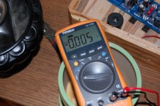
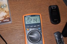
First pic is bias
Second pic is offset
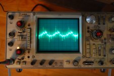
Third pic is Haystack.
Fourth pic is DC noise.
First scan is bias
Second scan is output layout
All assumes correct order of pics and scans😀
trsnformer shield not grounded.
Gotta to soccer practice. Be Back in a bit!
Edit:
ZM, Based on listening to F5T with and without cascoded FE, I prefer straight FE with no cascode. Seems to have better transparency, dunno.
First pic is bias
Second pic is offset
Third pic is Haystack.
Fourth pic is DC noise.
First scan is bias
Second scan is output layout
All assumes correct order of pics and scans😀
trsnformer shield not grounded.
Gotta to soccer practice. Be Back in a bit!
Edit:
ZM, Based on listening to F5T with and without cascoded FE, I prefer straight FE with no cascode. Seems to have better transparency, dunno.
Attachments
Last edited:
- Home
- Amplifiers
- Pass Labs
- F6 Amplifier