If he bundled parts (maybe Pass SIT?) with boards on his passdiy.com like Pearl 2, that would be fine. 😛
Well, my use of cascodes in the F6CC Teaser http://www.diyaudio.com/forums/pass-labs/216616-f6-amplifier-454.html#post3527718 is not to shield from high voltages but to minimize the non-linearities in the output MOSFETs caused by the Early effect and to mimimize the Miller capacitance effects from the output MOSFET Cgd. This cascoding still allows the same rail voltages and power dissipation as in the F5 and other FirstWatt products.It's my understanding that Nelson has a whole shed full of Firstwatt chassis, and the matching 300VA 18V+18V transformer... Those 2 items being "standard" will dictate a couple of parameters -- dissipation and rail voltage.
Casocded outputs usually being used to shield delicate devices from higher voltages, your guess is likely spot on.
hahahaha you will never catch up with big papa!!! He is a teaser 😛. as soon as you start building his latest masterpiece...He comes with a new one!. I guess if We jump ahead and start build the F10 We can catch up with him...the problem is to find out what new design and topology will He use in the future😕 I bet that big papa can build an amp with one transistor and a power supply😛

In addition to your approach of Teasr F6CC, I'll post a picture of 2 other possible mods of diyF5 which may promise a different sound [same loudspeaker] from the parent.How about a megaphone?😛
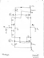
Mod diyF5
Picture of a simplified proposed circuit is attached:
In addition to your approach of Teasr F6CC, I'll post a picture of 2 other possible mods of diyF5 which may promise a different sound [same loudspeaker] from the parent.
Picture of a simplified proposed circuit is attached:
- Applies local instead of loop feedback.
- The input impedance of the front end is low; within reason.
- The joined gates of the front end is a summing junction
- Summing junction [bullet 3] receives Black-style feedback in complementary fashion from the source ports of the output MOSFETs. Or this summing port receives Pass-style feedback instead; by connecting feedback resistors [R] to points A and A' [drains of the input JFETs]. Bias stabilization of the output stage may also be active.
- Each output MOSFET has its local negative feedback [drain to gate] via Rf. Note the simultaneous bias and local feedback [of MOSFETs] by using the series connected resistors [+Vc] Rl-Rf-Rf-Rl[-Vc]. May wish to put a DC blocking cap in series with each Rf instead.
Attachments
I am sure it will sound different, but:Picture of a simplified proposed circuit is attached:
...
The expected maximum output impedance is Zl. It'll sound diiferent from diyF5.
- The resistors from the source of the output FETs to the gates of the JFETs create global negative feedback.
- The all of the feedback currents will be sensitive to the rail voltages thus degrade the PSRR.
I'm done. My Queue is full and unfinished. If I mention another amp, My wife will smack me. I am enthralled in whole SUSY thing. Perhaps will find that simplicity wins the day. Dunno or Dumbo, whichever.
Thanks lhquam for your analyses. Will this global NF lower output impedance like that in diyF5?I am sure it will sound different, but:
- The resistors from the source of the output FETs to the gates of the JFETs create global negative feedback.
- The all of the feedback currents will be sensitive to the rail voltages thus degrade the PSRR.
AU-anon? For anyone (wives) who believes their life has been affected by someone else's audio obsession (addiction), either today or in the past.
I would think so. You should run a simulation and see.Thanks lhquam for your analyses. Will this global NF lower output impedance like that in diyF5?
Thanks lhquam.I would think so. You should run a simulation and see.
The all of the feedback currents will be sensitive to the rail voltages thus degrade the PSRR.
Yes, I think a regulated supply might come in handy.
😎
An added complexity which is absent in diyF5.Yes, I think a regulated supply might come in handy.
😎
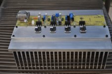
I received my F6CC Teaser boards and parts. Here is a picture of the build so far. Obviously the MOSFETs have not been yet attached with mica and grease. I am about ready for a smoke test.
This is a bench-test setup where the MOSFETs are attached using MOLEX connectors and elevated by a 1/4" aluminum plate which is attached to the heatsink with thermal grease and screws. This makes it easy to experiment with different MOSFETs be unscrewing them and readjusting the bias voltages. Also, using hex standoffs for power and output connections makes board removal easy in order to make component changes.
This is a bench-test setup where the MOSFETs are attached using MOLEX connectors and elevated by a 1/4" aluminum plate which is attached to the heatsink with thermal grease and screws. This makes it easy to experiment with different MOSFETs be unscrewing them and readjusting the bias voltages. Also, using hex standoffs for power and output connections makes board removal easy in order to make component changes.
Attachments
Last edited:
Looking good. Did you ever have any luck with dropping Rs. Using this technique. If so, I may try it with preamp I am playing with..
- Home
- Amplifiers
- Pass Labs
- F6 Amplifier