for 28V5 rail (and you'll get something as Vac x1.25 , when PSU is loaded ) , use 15K up to rail , 10K down to GND
remember that you don't need making heaters of cascode bias net resistors ......... so no need for so low value as you suggested
remember that you don't need making heaters of cascode bias net resistors ......... so no need for so low value as you suggested
for 28V5 rail (and you'll get something as Vac x1.25 , when PSU is loaded ) , use 15K up to rail , 10K down to GND
remember that you don't need making heaters of cascode bias net resistors ......... so no need for so low value as you suggested
O o forgot the current part... thanks Zen, will work on these values
for 28V5 rail (and you'll get something as Vac x1.25 , when PSU is loaded ) , use 15K up to rail , 10K down to GND
remember that you don't need making heaters of cascode bias net resistors ......... so no need for so low value as you suggested
Hi Zen, how much difference will it make if i keep both the resistances 10K, since the potential divider will just half the input voltage, in my case around ~14 V, guess that should work just fine
yes , even if I like them slightly cooler
So 15K is final...cooler, and splits the rail into half
The Toshiba JFETs operate at lower noise when the Vds is lowered below 12V.
15k/10k combo would be absolutely perfect at ~28.5V rail, I would run them a little lower actually maybe 18k/10k.
15k/10k combo would be absolutely perfect at ~28.5V rail, I would run them a little lower actually maybe 18k/10k.
Well there is something I am just not getting !!!. as I still cannot get a logical result from the formula =
rail volt /(R26+R28)*R28= cascode voltage
please what is *R28
(my rails are 34.5)
rail volt /(R26+R28)*R28= cascode voltage
please what is *R28
(my rails are 34.5)
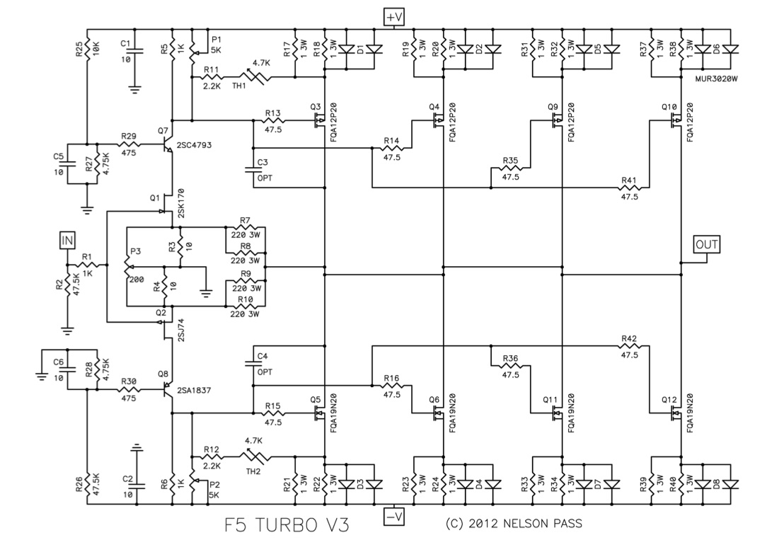
There is one error in this schematic - R26 should be 10K
Original documentation here -
http://www.firstwatt.com/pdf/art_f5_turbo.pdf
Last edited:
Long story short, with 34v rails the schematic values of
R25, R26 - 10k
R27, R28 - 4.75k
are perfect.
R25, R26 - 10k
R27, R28 - 4.75k
are perfect.
Hi, noob here. Could someone explain what has been done with the terminal block with the leads coming from the transformer? Looks like there are some resistors or caps that have been soldered in but I can find no mention of them in the BOM or on the PSU BOM or instructions.
Thanks,
John
Thanks,
John
The gatestoppers work essentially like a shock absorber at high frequency (way above audio) and damp the Mosfet from oscillation. The F5T is a pretty darn high bandwidth design and depending on a ton of variables it can oscillate. Higher value gatestoppers help damp that tendency.
BUT, if your amp works, don't worry about it. If it was going to break out in oscillation it would already have done it and you'd know because your Mosfet would be fried.
6L6,
May I ask if anyone has tested ferrite beards instead of resistors as gate stoppers like this one https://www.tme.eu/de/Document/2c95f46ee39e2edc46e38cef692acce0/fr.pdf
, so 1000 ohm at 25MHz...
I tried this in my tube gear (but with not so critical tubes) and It was giving me a nice upgrade, clearer, more dynamic...its basically a piece of copper wire...
Is this feasable to usein the F5T as well ?
I don’t know if anybody has done that with mosfets. I’ve only heard that done with tubes.
It would be simple to try.
It would be simple to try.
Happy to do so...what will happen of this thing starts to oscillate ? Smoke ? How do you know ?
Ok, this might be an experiment for later then...
In 2017, I built this amp, it work with 32V rails...I want to improve and implemented Peter daniel changes like no thermistor, no diodes and implemented the bridge thing for earthing...and got a big FLASH when switching on in the area of my power plug.
Amp was dead.
I never had the time to look into it again until now. I checked the PSU through - is OK, delivers from its 600VA 25V transformer through a CLC-Filter about 36V in idle / no loads.
Than I used my variac to power the amp up again...but the mosfets stay cold. No currenty at all measurable at the 0,5 ohm resistors.
Did I kill them or are there other points to check before ordering a new set of matched fets ?
- Home
- Amplifiers
- Pass Labs
- F5Turbo Illustrated Build Guide