biasing of output mosfets is referenced to rails;
with that approach , you'll have difference between rails for front end and ..... back end
so , no , not good idea
see- there is no such thing as stupid question ...... 🙂
with that approach , you'll have difference between rails for front end and ..... back end
so , no , not good idea
see- there is no such thing as stupid question ...... 🙂
They are???

Place diodes on same heatsink as Mosfets.
I strongly suggest cascoding if you use 32v rails.
Would you suggest retro fit cascode, for existing F5t, with 32 volt rails.
Regards
Many thanks Guys, as I've said before I'm a complete novice, but I do have the help, of a pass 5 builder who built his amps some ten years ago. They sound amazing.
Thank you for your help and advice.
Paul
PS he's on it
Thank you for your help and advice.
Paul
PS he's on it
As stated before I am planning the PSU wiring on my F5T build, so far I have seen 2 "methods":
1: Wiring the FE board and the OP boars directly to the PSU (1 connection each)
2: Daisy-chaining, that is wiring the FE to PSU and then from the FE to the OP boards.
Question: IF daisy-chaining wouldn't it be better to connect the OP boards to the PSU and the chain the FE to the OP boards ?
I "think" the higher current in the OP boards should be connected first, at least this is what I have seen in other design (audio, but not power amp).
Thanks in advance,
Max
Hi friends
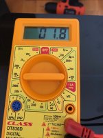
i have completed my f5 turbo project but couldnt set the bias. I ran out of trimmer turns. Dc offset is 1.8mv and didnt change during bias. Source resistor voltage stayed 0mv. Mosfets did not heat up.
I designed the amplfier two monoblocks each standard 50watts f5turbo. Fe board stuffed like cascoding. Each amplifier has its own 600va tansformer with +-35 volt dc unloaded.

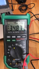


hi sangramVoltage across JFET source resistors (10 ohm)?
do you mean R3 and R4? near the P1 and P2
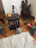
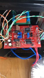
First doublecheck your wiring, you've got a lot that's the same color, it's easy to make a simple error.
Also verify that the cascode transistors are installed properly.
Is there a fan in that case? You will absolutely need one, those heatsinks are incredibly undersized for passive cooling.
Also verify that the cascode transistors are installed properly.
Is there a fan in that case? You will absolutely need one, those heatsinks are incredibly undersized for passive cooling.
First doublecheck your wiring, you've got a lot that's the same color, it's easy to make a simple error.
Also verify that the cascode transistors are installed properly.
Is there a fan in that case? You will absolutely need one, those heatsinks are incredibly undersized for passive cooling.
Dear 6L6
I checked the cabling will check again.
yes I have a 12 cm fan backside.
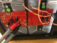
Did you mean by cascade transistors Q7 and Q8
They are Toshiba A1145Y and C2705Y
I am not sure about their orientation, did flat surface must look outside?
pls see the pic below (flat surface of the transistors looks inside)
Attachments
hi sangram
do you mean R3 and R4? near the P1 and P2
I don't have that PCB or a view of the schematic, so part numbers are difficult to decipher.
Dear 6L6
Since i am not cascoding (no paralel output boards for now) should i consider cancel those cascode transistors and short Q7 and Q8) if yes how can i short?
Since i am not cascoding (no paralel output boards for now) should i consider cancel those cascode transistors and short Q7 and Q8) if yes how can i short?
crackling sound during warm-up
Hi all,
I've some issues with my F5 turbo V2. All is playing very well, however I've strange crackling sound during warm-up on the left-side channel.
It is only the left channel, Power supply feeds both channels, so I can conclude this is not the issue. Right channel is playing silent and after warm-up also the left channel is silent.
Is there anyone who can tell where to start looking te remove this crackling sound. I thought of going over all solder-joints, however is this the right approach?😕
Nils
- Home
- Amplifiers
- Pass Labs
- F5Turbo Illustrated Build Guide