Hey, finally had time to work on these.
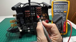
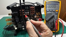
Green to ground is 406 ohms.
Orange to ground is 405 ohms.
Blue is super-high ohms (outside multimeter range)
Red is 0.5 ohms.
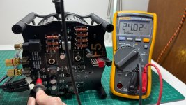
I compared to a couple of channels that are known good and found that the filter rails (green and blue) somehow collect a small floating voltage while nothing is plugged in. At the moment I'm reading +210 mV on the negative rail and +630 mV on positive rail but it does fluctuate over time. I don't think it's residual charge in the capacitors since this happens even after shorting the points to ground overnight. @Mark Johnson have you seen anything like this on the non-integrated AmyAlice filters?
@TiVV4bemb Voltage in circuit unfortunately means that a multimeter isn't able to take accurate resistance readings. So the green and blue values don't tell us much. The orange and red points don't appear to collect charge. Orange value looks reasonable but your red reading of 0.5 ohms indicates that something is wrong there. A photo of the back side of the board could help pinpoint the specific issue. IMO it's probably worth the effort to clean up all the solder joints. I would recommend using your iron to reflow each joint with a bit of flux so they become smooth and shiny, then remove excess solder from any that are still bulging (like orange, maybe green) using solder wick.

It's either dielectric absorption (Wikipedia article HERE) or else it's a perpetual motion machine.
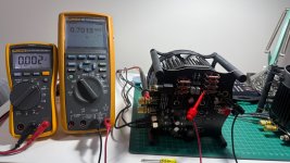
To check whether it's a perpetual motion machine, connect a 2.2K "bleed" resistor across the output and measure the voltage every 15 minutes. Take eight measurements (over two hours). If the voltage is nonzero after two hours then someone or something is continuously heating up the resistance element [ Power = Voltage * Voltage / Resistance ] despite zero input power. It's perpetual motion!
Dielectric absorption is much clumsier. As the Wikipedia article states, electrolytic capacitors are the worst of all (greatest dielectric absorption) and they take months to fully relax. If that bothers you, calculate your own value of bleed resistor and solder it onto the AmyAlice board's pins. Don't put it at the load, put it at the electrolytic capacitor -- on AmyAlice.
Attachments
Last edited:
Okay, my flux pen delivery has been delayed twice but should be here tomorrow. I'll try to upload better pics tomorrow and clean up the joints.I compared to a couple of channels that are known good and found that the filter rails (green and blue) somehow collect a small floating voltage while nothing is plugged in. At the moment I'm reading +210 mV on the negative rail and +630 mV on positive rail but it does fluctuate over time. I don't think it's residual charge in the capacitors since this happens even after shorting the points to ground overnight. @Mark Johnson have you seen anything like this on the non-integrated AmyAlice filters?
@TiVV4bemb Voltage in circuit unfortunately means that a multimeter isn't able to take accurate resistance readings. So the green and blue values don't tell us much. The orange and red points don't appear to collect charge. Orange value looks reasonable but your red reading of 0.5 ohms indicates that something is wrong there. A photo of the back side of the board could help pinpoint the specific issue. IMO it's probably worth the effort to clean up all the solder joints. I would recommend using your iron to reflow each joint with a bit of flux so they become smooth and shiny, then remove excess solder from any that are still bulging (like orange, maybe green) using solder wick.
A long time coming, here's the video build guide for the F5m Redux!
It's nearly an hour long so there are chapters if you want to skip around to a specific step.
It's nearly an hour long so there are chapters if you want to skip around to a specific step.
Hi,
I recently got this kit and have them soldered and assembled.
I thought this could be an easy one for me since i have built the B1K and ACA. I have done all the necessary test based on the fantastic video build guide, except that i have problem biasing them (both channels). No matter how many time i tried, the voltage across both R6 & R7 just refuse to go beyond 5mV both my multimeter. I thought I have checked all the solder joints and components orientation, but just couldn’t figure out what has went wrong.
I have done the quality control resistance and voltage (+/-24V) check, but when i measured the voltage at R7 reference to ground, I am seeing only -14v, where at R6 I am seeing a +24v. I wonder that could give some clue to what may have went wrong.
Hi Cheng,
It is odd to have the same problem on both boards. Can you measure the negative rail closer to the input (like at FB2) and share the result? Did you try swapping power supplies?
It is odd to have the same problem on both boards. Can you measure the negative rail closer to the input (like at FB2) and share the result? Did you try swapping power supplies?
Hi Nelson,
Here are what I tried. Swapping out the pair of power supplies got the same measurement.
FB1 : 24Vdc
FB2 : -24Vdc
R6 : 24Vdc
R7 : -15Vdc
Rgds
Here are what I tried. Swapping out the pair of power supplies got the same measurement.
FB1 : 24Vdc
FB2 : -24Vdc
R6 : 24Vdc
R7 : -15Vdc
Rgds
Attachments

I tried swapping out your supplied smps with the aca (pair) meanwell smps from diyaudiostore. I observed a beeping sound when i connected them to the board. Measurement as follow before i switch it off.
FB1 : 24Vdc
FB2 : 0Vdc
R6 : 0Vdc
R7 : 0Vdc
Rgds
FB1 : 24Vdc
FB2 : 0Vdc
R6 : 0Vdc
R7 : 0Vdc
Rgds
Attachments

Can you measure voltages on each connection for Q6 with the switch on and with it off? It's the only thing I can think of that would drop voltage between FB2 and R7.
Your measurement with the meanwell supplies suggests a short or partial short to ground somewhere in the negative power rail filter. C3 or C4 are the most likely candidates, but I'd like to try narrowing it down before having you desolder parts. Please measure FB2 with the meanwell supply, again with the switch in both off and on position.
Your measurement with the meanwell supplies suggests a short or partial short to ground somewhere in the negative power rail filter. C3 or C4 are the most likely candidates, but I'd like to try narrowing it down before having you desolder parts. Please measure FB2 with the meanwell supply, again with the switch in both off and on position.
Ok thanks Nelson. Will have them measured when i am back to the man cave on next weekend and report back.
Can you measure voltages on each connection for Q6 with the switch on and with it off? It's the only thing I can think of that would drop voltage between FB2 and R7.
Your measurement with the meanwell supplies suggests a short or partial short to ground somewhere in the negative power rail filter. C3 or C4 are the most likely candidates, but I'd like to try narrowing it down before having you desolder parts. Please measure FB2 with the meanwell supply, again with the switch in both off and on position.
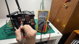
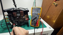
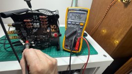
Manage to find some. Here are the measured value as requested.
Additionally i tried measured the resistance on the rail of c3 & c4 reference to ground as suggested by Birdbox photo. There are a few hundred ohms measured. Compared to c1 & c2 which have mega ohms measured.
Q6 (original smps)on condition
Q6 (original smps)off condition
Q6 (meanwell smps) same for both on/off condition
FB2 (meanwell smps) same for both on/off condition
I would suggest removing C3 and C4 then measure ohms again from their larger pads to ground. If that gets rid of the short, then you can do a temporary fix by soldering a wire across the large pads for biasing and I can send replacement caps. Here's an example photo.

If you haven't already, turn your potentiometers back to zero before attempting to bias again
If you haven't already, turn your potentiometers back to zero before attempting to bias again
Earlier on I have removed c3 & c4. Below are the value measured.
Does the 287ohm measured value at c4(3) reads normal to you?
Or could it be Q6?

Does the 287ohm measured value at c4(3) reads normal to you?
Or could it be Q6?
Could be Q6, could be R17. In your photo above, Q6 looks cleaner than R17, so I'd start with the resistor.
Removed r17 and I am still getting the same value as above.
Removed and measure Q6 resistance.
d to s - 232ohm
d to g - 272ohm
s to g - 48ohm shorted
Switch to diode mode to measure d to s of Q6 based on google ai.
0.19vdc measured with both probes orientation.
Removed and measure Q6 resistance.
d to s - 232ohm
d to g - 272ohm
s to g - 48ohm shorted
Switch to diode mode to measure d to s of Q6 based on google ai.
0.19vdc measured with both probes orientation.
Special thanks to Nelson, I managed to replaced Q6 on both channels, measured the resistance to gnd (getting Mohm) and bias them. The biasing took a while, but nothing complicated, especially with the fantastic video guide.
Strangely, I connected them to the bridged ACA meanwells just to double check of any further partial short and I am still hearing the beeping sound from the meanwells.
Switching back to the original ps and decided to just swap them in with the ACAs on my desktop setup. The additional watts really make the pair of ufonken sound more effortless., but I am hearing some high frequency noise from the speakers, probably due to the high gain of the B1K. Will try to figure it out tomorrow.
Attachments
Hi,
Just a follow up post showcase and share this wonderful F5M redux. I have shifted the B1K > F5M > BIB speaker as shown in attached photo. The combination is really great. I am using this setup mostly on Jazz and it exceeded my expectations. Thank you Nelson and the community once again.
Wil
Just a follow up post showcase and share this wonderful F5M redux. I have shifted the B1K > F5M > BIB speaker as shown in attached photo. The combination is really great. I am using this setup mostly on Jazz and it exceeded my expectations. Thank you Nelson and the community once again.
Wil
Attachments

I seem to have that similar issue, however, I also have a bulging capacitor C6, that definitely need to replace regardless.....and trace the whole circuit as well to make sure all is well otherwise..........especially since I went into my office the other day and somehow the fan was running and heatsink was slightly warm, even though the I had the power witch in the off position (I hope nothing else was damaged). BUT, also before I go through and double check everything, I wanted to ask/double check and make sure since I have extra keratherm around; Is it okay to use keratherm vs the grease on the bigger, ie IRFP 140s etc? I used it on the bigger mosfets on the sink just because I have no other use for them at the moment and wanted to rul out all other potential variables, besides those listed in the thread already.
- Home
- Amplifiers
- Pass Labs
- F5m Redux