The smaller hole actually saved me from making a dumb mistake... messing up my clean output pad... that would have sucked. ( of the powered solder sucker kind )
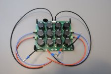
Just posting some pictures of what I have so far, in case I've done something wrong.
Attachments
-
 IMG_0481.JPG27 KB · Views: 181
 -
 IMG_0471.JPG78.1 KB · Views: 179
 -
 IMG_0472.JPG66 KB · Views: 189
 -
 IMG_0484.JPG56.3 KB · Views: 186
 -
 IMG_0482.JPG53.8 KB · Views: 202
 -
 IMG_0480.JPG44.3 KB · Views: 186
 -
 IMG_0474.JPG75.2 KB · Views: 186
 -
 IMG_0473.JPG88.8 KB · Views: 185
 -
 IMG_0485.JPG84.5 KB · Views: 186
 -
 IMG_0486.JPG86.1 KB · Views: 177
 -
 IMG_0477.JPG99.1 KB · Views: 185

Oh man, @roboDNA . You're making good progress! You're gonna have an amazing sounding amp in the near future. Kuddos!
@roboDNA - Looks like some nice work! There's nothing (that I see) that is "wrong". With that said -
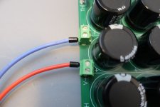
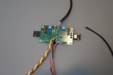
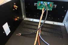
If I'm understanding correctly, you're taking the red and white insulated wires and pairing them for the input + signal. Those will go to the center of your input RCA jack. The stranded "lone" copper strands typically used for the shield and connected to ground on the PCB will go to the tab on the RCA.
It's not incorrect, per se, but I admit that I don't love that you used both black and brown for your ground to the amp boards. Since you have brown for the ground for one connection, I'm not sure why you were not consistent. You've used black (traditionally more appropriately) for your mains live / line / hot. It's only for you, so it's not a big thing. It's an eeensy weensy thing. Don't change it, but I wanted to mention it.
Either way... it looks like you're well on your way to a great amplifer.
Last edited:
@ItsAllInMyHead you have a good eye! I was curious to find out how quickly someone would notice the black wire 🙂 I did NOT have grey wire and was out of options for colors so pulled the trigger on the black. I agree it's not consistent and was already thinking of fixing it. ( I have yellow, red, green, brown, black, red and white so would need to order more colors )
^ My personal preference, since there are no hard-fast rules around this for DIY is:
Use the wiring per code/accepted norms for AC mains. In the US, it's black / white / green or green with yellow stripe.
For DC, it's an anything goes sort of thing, but I don't use colors that overlap with AC mains.
My preference in your case would be to use brown for both 0V (GND). They're identical and either one could go to either location (speaker or PSU).
My goal (for myself) is consistency. When I look inside one of the many, many amps I've built, I want to be able to know by my own "code" exactly what each wire represents. That way, I potentially remove one opportunity for error / injury.
Edited to add - For people in countries where blue / brown are used for AC mains... this may seem like a HORRIBLE recommendation / preference. I acknowledge that. When we do build guides... which eventually MAY cover some AC mains wiring... we'll have all this sorted.
Edited - I hope for clarity. 🙂
Last edited:
You should not need to drill holes. Deluxe chassis should all assemble without the need to drill.
The one thing you could drill is a dedicated spot for the chassis feet. However I have never done that and instead get some longer M3 bolts and use the mount points for the bottom plate to both mount the chassis feet and bottom plate.
The one thing you could drill is a dedicated spot for the chassis feet. However I have never done that and instead get some longer M3 bolts and use the mount points for the bottom plate to both mount the chassis feet and bottom plate.
Last edited:
Ok thanks. I now see the screws are tapered and so are the pre-drilled holes. Good thing I didn't get the drill out!
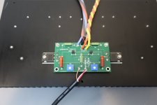
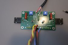
What is the best way to attach spade connectors to the PEM leads? When I try to push them on, they seem very tight and actually damaged the PEM. The PEM lead pushed into it's plastic case and could not take the force needed to get the spade connector attached. I have the correct size connector, and the larger size would allow it to move left to right so it's too large. I managed to use plyers to pull the PEM leads out but not sure if it's safe to use them PEM as it may be damaged inside. I'll use a different one but do not want to damage that one as well. I could widen the spade with plyers and then tighten them back up after attaching but would rather try to do it the right way.
Last edited:
I have not had that issue with the 0.187" or 0.25" faston female spades I've used. Did you try putting on an uncrimped spade with no wire to see how that fits? Maybe the crimping process caused some deformation of the spade portion.
Yes, I usually solder all three wires to the PEM. Then there is no possibility of the wires working loose. There is no need for me to ever disconnect the wires from the PEM, so I see no need to add extra parts and have a possible issue of loose connections.
The PEM part of the build has become a 'hack job' on my end. So far, I've butchered 2 PEMs. I wasn't able to solder wires to the leads as the space in the PEM case is tight. It's difficult to avoid the iron touching the plastic. The amount of heat needed to be applied to the leads melts the bottom part of the lead, shifting it from it's original position. ( the lead I heated up is now crooked ) I"m not sure if I've melted something inside of the PEM. Even though I was able to tin the wire and the lead, I could not get enough heat to solder them. Having so much difficulty with the first lead, I imagine it will be more difficult as I add wires. The spade connectors are not reliable and also seem 'hackish' to me, but I may need to try again using those unless someone has a suggestion. So far, I've noticed the spade connectors can be pulled from the wire fairly easily even though I used the 'expensive' tool meant for that job. ( even the small red ones ) The spade connectors I have don't fit easily onto the lead, and not possible to attach by hand. ( had to use pliers to get them on ). I could try widening the spade slightly and then using pliers to tighten, but not sure that is 'secure' enough. Being the entry point for power, I am hoping I can make this part of the build as clean as the rest.
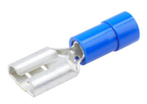
I always just use some quality Faston's like this. I use my heat gun to soften the blue plastic part and throw that away. Wire is inserted and tightly crimped as normal, and then soldered (belt and suspenders). And finally whole thing covered with heatshrink, sometimes I even double up and use two layers of that...
Attachments
I was thinking I have bad spade connectors, so trying the Fastons sounds good. I ordered different spade connectors for the output posts and those seem very solid. I did not try soldering the spade connector to the lead instead of bare wire... I should have tried that instead. What is belt and suspenders?
I suspect I have a bad batch/low quality/non-standard-sized spade connectors. I bought them on amazon and they seem different than another batch I purchased for the output posts. Those seem solid and fit perfectly onto the post leads by hand.
I suspect I have a bad batch/low quality/non-standard-sized spade connectors. I bought them on amazon and they seem different than another batch I purchased for the output posts. Those seem solid and fit perfectly onto the post leads by hand.
YES! Belts and suspenders! good one. i like it.
Do you also solder the Faston spade connector to the lead, or just the wire to the spade?
I should also ask: What sizes of Fastons do I need for the whole build? Some leads are smaller than others. I'll be ordering more today.
I ordered these and suspect they are not high quality:
Problematic spade connectors
And these worked well:
Good Connectors
Not sure if the sizes are different standards and could be slightly different, explaining why I could not get them on without damaging the PEM lead.
I'll also try ordering TE Fastons as they are sure to be high quality.
Last edited:
- Home
- Amplifiers
- Pass Labs
- F5m kit