Last successful builds were a few A75, 25 years ago, still working and the caps are from that era.You can use larger capacitance up to a point. Just remember the inrush current is more (which taxes your thermistor, power switch, etc…). For more details and calculations, see my post here. If this is a new build or you are a new builder, suggest sticking with the original design so your maiden voyage is without fireworks. I personally try to limit as much ptp wiring as possible to minimize points of failure.
Best,
Anand.
So practically a 25 year old virgin.
I will just go with the design, too little time left to muck around.
But I still have that text book gifted to me by my then GF that I learnt a lot from, by Messrs Horowitz and Hill.
You can always grab an extra transformer and use those caps to build a PS for bench use. I'm thinking about adding a bypass switch to my DBT and leaving the FW bench supply permanently connected to it for added convenience.
Excellent book, a reference! And Also Bob Cordell’s Designing Power Amplifiers book. PM me off line and I can suggest more that may be better to ease into the hobby since Horowitz and Hill would probably be more apropos for 1st semester EE’s.But I still have that text book gifted to me by my then GF that I learnt a lot from, by Messrs Horowitz and Hill.
Best,
Anand.

JKiriakis,
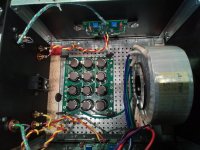
Good work with the DIY chassis build from scratch - looks like the build is coming along nicely. 🙂
Good work with the DIY chassis build from scratch - looks like the build is coming along nicely. 🙂
Slowly building the f5m and am confused with the the revised ps board (V1R1) connections. I've been referring to 6L6's excellent photos throughout but those use the original ps board. Could someone share a photo of their wired completed V1R1 ps board please. I reviewed NP's revised schematic but it isn't clicking with my brain box.
Attachments
I don't have pics to offer you, but where are your rectifiers?
Connect primaries properly to mains. See various methods in other build guides or forum member pics. Edited to add - note that the thermistors for inrush current limiting are on the PSU PCB if you're referencing other common First Watt PSU wiring examples to connect mains to your primaries.
Connect secondaries properly to rectifiers.
Don't connect amp boards to PSU PCB yet.
Don't connect rectifiers to PSU PCB yet.
Check DC output of the rectifiers to ensure all is good using any one of many proper check methods / safeguards (DBT and/or Variac being common).
Once you have that all ready to go, post back.
All the wiring above - could/should be identical to the previous board revision (I think).
Others will surely have more / better ideas and may have some photos.
Haven't attached the rectifier or PS board yet, just laying it out for now while I wait on the terminal strip and safety cap to arrive. I'll check the rectifier output first as advised, I have a small variac for that purpose. Glad you told me to check that first as I was going to connect the PSU to the amp boards today but will delay that. I spend a lot of time reviewing other's builds, relevant postings, etc. to build my knowledge and understanding, not just paint by numbers. It's a steep learning curve for me being new to DIY, just very appreciative of this forum. Will post back in a few days, many thanks!
It's a steep learning curve for me being new to DIY

Me too.
You don't have to do it that way, but to give credit where credit is due, I think it was Ben that continues to stress to check one step at a time, particularly on the first run. When there's even the slightest of chances that a reverse voltage results in big caps going kaploowee, or a very large mains surge, or breakers tripping b/c I got primaries wired incorrectly, I try to take every precaution.I'll check the rectifier output first as advised, I have a small variac for that purpose. Glad you told me to check that first as I was going to connect the PSU to the amp boards today but will delay that.
So, after sorting and identifying each of your primaries and secondaries you may...
Wire primaries to mains => Check AC at secondaries / pause or move on as needed. I'd use 6L6's gorgeous pic from earlier in the thread as a reference. I would remove the thermistor and leave the safety cap.
Wire secondaries to rectifiers => Check DC at rectifiers / pause or move on as needed.
If any of that doesn't make perfect sense, I can try to explain further with a diagram or two (which should be validated by an actual expert)...
Mainly... have fun!
Edited for clarity and a link - here... https://www.diyaudio.com/community/threads/f5m-kit.408290/page-41#post-7628684
For all - edited yet again - I read enough to where I THINK the new PSU boards don't necessitate using another inrush current limiting thermistor "off board", in addition to the ones on the board that serve dual purpose, but please correct me if I misinterpreted.
Last edited:
Most of the fellas are using 200-300VA transformers, so in all honesty, a thermistor on the primary side is optional, not required. Remember the inrush current happens on the primary side and we want to save the switch, and transformer since the capacitor banks are essentially empty at time zero of turn on. The more the capacitance, the larger the toroid (at >400VA), the larger the inrush current. Tom C has written enough about it here. But given that many who are building this F5M may be completely new to this diy audio build thang, simplicity is nice.For all - edited yet again - I read enough to where I THINK the new PSU boards don't necessitate using another inrush current limiting thermistor "off board", in addition to the ones on the board that serve dual purpose, but please correct me if I misinterpreted.
Good find on 6L6’s build, post number 806 should be a sticky.
Best,
Anand.
6L6's post #809 was what made me order the terminal strip, it seems easier than trying to work the thermistor and 3300 pf safety cap into the tight confines of the IEC module. Since I'm using the Antek 4218 I'm assuming the thermistor would be a good addition as 6L6 used?
I'm assuming the thermistor would be a good addition as 6L6 used?
Noting to do with me, Nelson put it on the schematic. So building it as designed is always a great place to start.
🙂
Understood. Looking forward to the updated photo of the new PSU board later. Your excellent photos have been very helpful as has Anands explanation of the trafo wiring in post #1454.
Here’s some quick n’ dirty photos as I put things together. More to follow.


It's a steep learning curve for me being new to DIY
I'm in much the same situation. I don't think it's easy for the long-term experienced to see/remember how much you can build up to this point without anything more than the ability to solder things in the right way around.
It's a pretty big jump from that reading and understanding circuit diagrams, and wrapping your head around the whole concept of power supply from AC and all the associated tools and procedures that you haven't touched until this point - the understanding of which seems to be presumed in most of what you read, and which can most definitely kill you dead. It's a significant barrier to making headway in the hobby.
I've been spending my time reading every build guide I can find, as it seems that each one will have some little nugget in there that the others omit, as well as asking a lot of probably silly questions here (and generally receiving some very patient answers). I've also been slogging through various beginner electronics texts. There's a lot of irrelevant info in them (I'm not sure I'm ever going to need an understanding of what a British Thermal Unit is), but once every few chapters something absolutely crucial clicks into place.
In short, I'm right there with you on this one (or at least I will be once I have a chassis for my build). 🙂
- Home
- Amplifiers
- Pass Labs
- F5m kit