Had a little set back tonight.
A little too much much bending action on those wee little input wires on one board.
I thought I was being very conscious about it too.
Anyway, I was fortunate enough to wick the joints and re-solder it in place, holly sucker balls, did I get lucky.
Anyway, this is what I have created.
A little too much much bending action on those wee little input wires on one board.
I thought I was being very conscious about it too.
Anyway, I was fortunate enough to wick the joints and re-solder it in place, holly sucker balls, did I get lucky.
Anyway, this is what I have created.
Attachments

@flamethrower - can't wait to read your reaction after it fires up and you have tunes. Keep on keepin' on.
 almost there
 Help -where?
Where do I go and cry my heart out, when my new F5v3 build blows the fuse immediately and no LEDs come on at all. In other words, where is the F5 builders forum.
Where do I go and cry my heart out, when my new F5v3 build blows the fuse immediately and no LEDs come on at all. In other words, where is the F5 builders forum.
are you using a light bulb? do you have fast blow fuses? what max amperage are they?
if yes to all , you have a short (most likely to ground) somewhere
a simple approach would be to disconnect the power supply from the amp boards
1. test the psu - if it works
2. connect one channel at a time and test
- make sure that neither the positive nor negative rails are continuous with ground before you start.
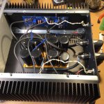
Hi bBel. Thanks for your feed back. I also suspect the power supply, as both channels do exactly the same - no LEDs light up and all 4 x 0.47R/3w resistors get hot and emit smoke plus the 3amp slow fuse blows. But I did measure the power supply before hooking things up. I have to measure it gain. Funny, my builds normally work.
If the resistors are getting hot you have lots of current going somewhere, so let’s take a look and see what we can see.
Please post well-lit, in-focus photos and many members with sharp eyes can look for what needs to be changed. 🙂
Please post well-lit, in-focus photos and many members with sharp eyes can look for what needs to be changed. 🙂
Are the bias pots set to full-on vs. full-off? Easy to do depending on which build guide you’re using.
Counterclockwise may be full on. With the power off you need to measure resistance across R5 and turn P1 so that resistance is zero or as low as you can get it, and then do the same with R6 and P2. That is the only way you can guarantee the bias to be set to zero at power up. 🙂
Also, only have one amplifier PCB connected at a time when testing the amplifier. Any fatal mistakes will only ruin one side instead of both.
Also, only have one amplifier PCB connected at a time when testing the amplifier. Any fatal mistakes will only ruin one side instead of both.
Also. check for cuntiniuty between sink and outputtransistors and between each leg of the outputtransistors. But my guess is that the pot's are turned the wrong way.
My pots are full on (max resistance) when turned counter-clockwise.
Mine also
And another thing, when isolating boards from the PSU for dialing the boards in,
is it sufficient to just disconnect the V+ at the PSU?
is it sufficient to just disconnect the V+ at the PSU?
Thank you, appreciated 6L6.
This pic pretty much somes up why my build took as long as it did.
I call it "project inventory mismanagement".
This is the first time I have taken on a project like this.
Building speakers or even turntables is where my "comfort zone" is I guess.
I have my light bulb tester done and plan on cooking this thing this weekend.
Fingers crossed, I will be listening to it sometime this weekend.
Thanks to all who have helped
Greg
Attachments
My pots are full on (max resistance) when turned counter-clockwise.
Mine also
It is easy to end up with the pots upside down which reverses it. Some of the build pictures have them that way. I have a couple paperweights with them mounted upside down.
Pictures
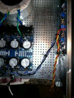
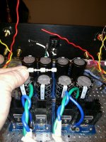
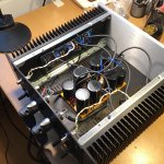
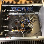
Here are pictures of my build. I will check the pots later today. Thanks all.
Here are pictures of my build. I will check the pots later today. Thanks all.
Attachments

- Home
- Amplifiers
- Pass Labs
- F5 V3