It seems like I'm saving at least $25 by putting together my own digikey order, unless I'm missing something.
This site help you to build your dream amp. I think it is only fair to buy from them in return. It's just plain logic and honesty.
That's 1, but you also save a lot of time doing so and their prices are just about excellent.
I guess it is probably a matter of mentality....
Take a look at what Nelson has to say about power supply capacitance:
https://www.passlabs.com/press/power-supplies-commentary-consumers
https://www.passlabs.com/press/power-supplies-commentary-consumers
People like to buy big caps. Seems like it should work better, and maybe perhaps it does. Maybe.
But it won’t work any worse, so use what ya got and don’t worry about it one bit.
But it won’t work any worse, so use what ya got and don’t worry about it one bit.
I like lots of caps. I just today finished squeezing in 3x the original amount of ps capacitance in an Adcom 5400 output stage, and sure enough, there's 1/3 the ps ripple just like the math says. And that was just for the output stage: A CLC on the input stage rails yielded less than 1/20 the original's ripple, to under 2mVAC.
Take a look at what Nelson has to say about power supply capacitance:
https://www.passlabs.com/press/power-supplies-commentary-consumers
Good read, thanks for sharing.

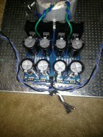
What is the blue round thing attached to the euro style terminal strip opposite the CL-60s?
Also I didn't see anything about the CL-60s in the BOMs.. (This isn't accusatory) I'm just curious where I was supposed to figure that out? In one of the schematics?
Also, if I'm using the soft start, does that mean I don't actually need the CL-60s?
Thank you in advance!
-Jesse
Blue round thing is a RFI suppression cap. Note that it must be X2 rated or better.
The two CL-60s on the terminal block are there to limit inrush, so you don't need them with a soft-start.
Cheers,
Jeff.
The two CL-60s on the terminal block are there to limit inrush, so you don't need them with a soft-start.
Cheers,
Jeff.
Just read through this whole thread and Flamethrowers journey (Any updates?).. I'm about to embark as well. I've got most of the parts on order. I'm looking forward to it. Previously, I've built the ACA and a ST-120 from Tubes4Hifi. (tubes4hifi amplifier KITs page)
I think I'm going to return my 18,000uF caps and get 22,000uF. I have cap envy.
Also I missed that the 4U deluxe is only 300mm deep and the 5U is 400mm.. Might have gone with the 5U if I realized.
Is there really no difference (other than cost) between using the diode section on the universal power supply or a monolithic bridge? The heat sinks alone are more than the monolithic piece.
What's a good way of deciding which transformer to buy? The 400VA antek seems like the one to pick, but just curious what kind of math I could do to come to that conclusion on my own.
Thanks!
-Jesse
I am building mine with a 3U chassis 400mm deep, I would go for the deeper depth which ever chassis you use.
Just my mileage I guess
Just my mileage I guess
I am building mine with a 3U chassis 400mm deep, I would go for the deeper depth which ever chassis you use.
Just my mileage I guess
This is a great plan—I stole this idea from flamethrower after doing the math (more sink than shallow 4U) —idea originating from AudioSan back in post #80, and blessed by 6L6 (for AJ). My AJ def runs cooler than some as far as I understand—and I got to drill and tap some holes. My F5 I built in the 4U x 300mm with an L bracket for the transformer—it was nice to have the mounting spec pre-drilled sinks on my first build... there was enough going on, but the L bracket was required if using the DIY stores diode bridge and leaving all the PSU boards attached....
Has anyone built the 50 watt version of the F5 (non-turbo)? He's saying it's possible, right?
"Increasing the power supply voltage is the obvious way to get more power out
of an F5. You can simply raise the supply rails to +/-32 Volts and get 50
watts into 8 ohms right away without other modification. 24 V AC secondaries
on the power transformer will do it. Don't forget to use higher voltage power
supply capacitors. Probably you should also upgrade R9 through R12 to 5
watt resistors. Depending on your heat sinking, you will probably want to
adjust the bias so that the power transistors don't run too hot."
It’s possible, absolutely. Things will run hot and you’re going to be right at the edge of operating specs of a couple components. As was suggested in your quote there’s a few component changes to look into, but those are simple substitutions.

Also, I had run across an article where NP explained how this amplifier works using a basic plumbing diagram.
I want to put that diagram on the front of my amp, may sound kind of different to some people, I however find it fitting.
If someone could post a link, it would be appreciated.
Thanks, Greg
I want to put that diagram on the front of my amp, may sound kind of different to some people, I however find it fitting.
If someone could post a link, it would be appreciated.
Thanks, Greg
Also, I had run across an article where NP explained how this amplifier works using a basic plumbing diagram.
I want to put that diagram on the front of my amp, may sound kind of different to some people, I however find it fitting.
If someone could post a link, it would be appreciated.
Thanks, Greg
It's in the F5 manual which you can download from the First Watt website and also here:
You can DIY! The F5 Power Amplifier | audioXpress
- Home
- Amplifiers
- Pass Labs
- F5 V3