cascode referance voltage = rail voltage/(R25+R27)xR27
so for 50V rails it will be:
50/(10K+4.75K)x4.75K= 16.1V
for 32Vrails:
32/(10K+4.75K)x4.75K= 10.3V
Audiosan,
Proved these work in real work measurements.
Thank you.
Biasing seems a little trickier than standard F5.
I am going to do some more testing of values for R5,R6. I think I will go to 2.2K from 1K.
I find as the voltage climbs, my pots have limited and timid offset adjustability. I removed the thermistors to see if it helps, and it does not. Makes it easier to set bias for me.
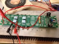
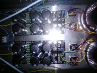
Attached Pic 1 -Cascoded version running 48V, Jfets at ~16v
PIC a version 2 one running strait out.
Attachments

good to hear 🙂
what is your bias goal? and how many outputs?
Well, for testing 1,2,3 and 4 🙂 I am trying to build several variations to cover functionality of the board and part behavior.
But does this affect Bias? Both version 2 and 3 schematic show same R values here for R5,R6 - P1,2.
the bias will affect the adjustmet of the pots. so for high bias,
it migth be good to change the value of the resistors.
one must just try and see what works best 🙂
it migth be good to change the value of the resistors.
one must just try and see what works best 🙂
Tea Bag are selling any power supply boards?
wrong thread for my boards - but not currently. I am considering.
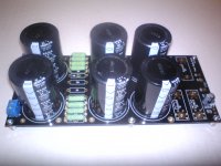
I would recommend the one from chip amps.com under the Aleph PS section. If you look around you can get some decent size bug caps on it, plenty of space for 5 .47R resistors and a place for 2.2K 5W bleeder resistors. And six big caps, 4 TO-220 type diodes can go here, and each can have a 2" tall heatsink. I will try to post a pic of one, if nobody has one quickly. It's <10.00usd. That's hard to beat!😉
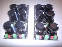
here is 3 without the diode's🙂 one with 6x10.000uF 80V
2 with 6x12.000uF 35V
they all have 2.2Kohm bleeders and 4.7uF bypass caps. CRC resistors is 4x0.47ohm on one. and 5x1ohm on the 2 others.
2 with 6x12.000uF 35V
they all have 2.2Kohm bleeders and 4.7uF bypass caps. CRC resistors is 4x0.47ohm on one. and 5x1ohm on the 2 others.
Attachments
Last edited:
Everyone is hopelessly addicted to the F5 amp.
What have you done Nelson?
You have created a conundrum
What have you done Nelson?
You have created a conundrum
 he released a decic
Has anybody seen a currently available PS board for dual secondary transformer? Or even just a board for the rectifiers (TO 220) There have been some around, but I don't see any available right now. Sure would be nice to see something with thick traces and hefty plated holes. Heat sinking 4 devices/rail is a PITA
have not tryed them. but they are not driving dual rectifiers? are they?
i think they are singel rectifier and commond ground.
i think they are singel rectifier and commond ground.
how about the ones they sell here in the forum store P-PSU-1V20 - PSU Cap Diode Board - Boards 🙂
No diode heatsinks?
.No diode heatsinks?
This is the issue.
For those of us who think our discrete devices have some impact on overall sound.
Guys what voltmeter accuracy would you consider adequate for adjusting the bias/offset?
Would a 10mV error be acceptable (Keeping the max acceptable offset reading at 40mV to compensate)
Would a 10mV error be acceptable (Keeping the max acceptable offset reading at 40mV to compensate)
- Status
- Not open for further replies.
- Home
- Amplifiers
- Pass Labs
- F5 Turbo is posted