Thanks for the responses!!!!!!
For the 2SK170 and 2SJ74, 2 pair for $200. I sent him another e mail to see if that was in US$. Hope not. But yes, he seems to be the MAN.
Wonder where he procured them?
Thanks
Paul
It should be HK$.
Work in progress
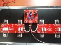
The first channel is complete 😀
The connection of the +V, -V and Output will be on the remaining holes of the O/P PCB but I have a doubt about the ground connection to avoid the ground loop issue.
I attach also the TH's picture. Seems that the only place to glue it is in that position but I remember that the best is directly to drain pin of the FET.
Any suggestion is most welcome 🙂
Attachments
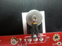
Thermistor on Fet screw is perfect. Ideally, you would like all ground to route through main board and go to PSU. This becomes your star ground point, with only single wire going to the PSU. Looks very clean so far.
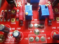
What is the correct size for R3, R4? Im currently using 0.25W. Is there any reason why the store board is designed for 1W?
Thermistor on Fet screw is perfect. Ideally, you would like all ground to route through main board and go to PSU. This becomes your star ground point, with only single wire going to the PSU. Looks very clean so far.
Hi Buzz... As you see in the picture now I have the ground from the FE to the 2 output board plus the shield of the signal cable. If I well understand I will route 1 cable for the ground from one of the holes free on anyone of the output board to the PSU. The ground of the 2 PSU (+V and -V) will be shorted and this will be the star ground.
It would be better if you could double u on one of the inputs on the FE board. THis would be your branching point. You are encountering one small quibble with boards. Not quite enought holes for ideal wiring. THat being said, it worked perfectly for me with slack wiring job.
Your welcome. It would be nice if you have a variac to bring up the amp. I sent out high Idss fets, so the bias will come up quickly.
Those who built FT5 said that diodes does not heat up much, wouldn't it be better to mount separate ALU bar for diodes on both sides mounting perpendicular to board? This way you could lower the FET a bit putting it on the center of these 5U heatsinks, allowing for higher bias.
Actually I don't have a variac but I will use the "bulb" metod firing up the PSU first.
About the star ground point... as you suggest will be on the FE board adding a small hole 🙂
About the star ground point... as you suggest will be on the FE board adding a small hole 🙂
emyeuoi,
I like it.
Rolandong
They do not get warm at all. Either way you do it, you want them thermally connected so that they track each other. I haev done both ways and have not noticed any audible differences, but then again, I do not have a hard load for the amp.
I like it.
Rolandong
They do not get warm at all. Either way you do it, you want them thermally connected so that they track each other. I haev done both ways and have not noticed any audible differences, but then again, I do not have a hard load for the amp.
What is the correct size for R3, R4? Im currently using 0.25W. Is there any reason why the store board is designed for 1W?
Yes, there is. We discussed this back when Toecutter was designing the boards.
This is a Turbo amp and we expect to use turbo power.
You need to consider the AC power dissipated in the feedback circuit.
R7,8,9 and 10 are rated at 3 watts each for a reason. They will see all the voltage across the speakers, feeding some of this back to R3 and R4. So R3 and 4 should be rated at least at 1/12 of the wattage of the feed back resistors = .5 watt plus the current generated from their idss, which isn't much.
For a V3 amp, you may want to look at uping all these resistors wattage, depending on expected voltage output design.
Hope this helps,
Rush
I shipped 1W with the kits. Depends on the version as well as the load. I don't think a v2 is an issue. V3 may be a concern, but in that case, it becomes about the load.
Yes, there is. We discussed this back when Toecutter was designing the boards.
This is a Turbo amp and we expect to use turbo power.
You need to consider the AC power dissipated in the feedback circuit.
R7,8,9 and 10 are rated at 3 watts each for a reason. They will see all the voltage across the speakers, feeding some of this back to R3 and R4. So R3 and 4 should be rated at least at 1/12 of the wattage of the feed back resistors = .5 watt plus the current generated from their idss, which isn't much.
For a V3 amp, you may want to look at uping all these resistors wattage, depending on expected voltage output design.
Hope this helps,
Rush
Hi Rush,
Very clear indeed....Really appreciate your detailed explanation....
Cheers.
- Status
- Not open for further replies.
- Home
- Amplifiers
- Pass Labs
- F5 Turbo Circuit Boards