Things are looking good! PSU could use another pi resistor or two as you surmise, your transformer is perfect.
Yes, omit the diodes.
Still a little fuzzy how the heatsinks will mount to the boards, etc… but looking forward to seeing how it plays out.
Cascode the input Jfets if you're not planning on it, at those rails you must have them.
Yes, omit the diodes.
Still a little fuzzy how the heatsinks will mount to the boards, etc… but looking forward to seeing how it plays out.
Cascode the input Jfets if you're not planning on it, at those rails you must have them.
I appreciate your input and thanks! I've been refurbishing and modding amps for years with great success, but this is my first build from scratch so to speak. The more I build the more I learn. I really appreciate the time and energy you and many of the other major contributors invest to facilitate the education and advancement of the diy community!Things are looking good! PSU could use another pi resistor or two as you surmise, your transformer is perfect.
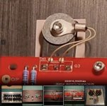
Here is a mock-up. I think 3 points of mounting will be adequate since the fet will be so close to the board I may be able to involve the wide part of the lead in the crown of the solder. I plan to space each fet exactly equal in all directions and am also considering the potential thermal effects of mounting the heatsinks to the chassis. Thinking of thermally isolating the heatsink mass from the chassis at the attachment points so that one area of the heatsink won't track differently than the other. Not sure if I will use the 1/8" base plate or tap the heatsink directly. Probably the latter.Yes, omit the diodes.
Still a little fuzzy how the heatsinks will mount to the boards, etc… but looking forward to seeing how it plays out.
For sure. Probably going to build balanced as well. Thanks !Cascode the input Jfets if you're not planning on it, at those rails you must have them.
PS is there a BA 2023 in the works?
Aha! Ok, I understand.
Balanced doubles everything, including heat. Keep the plan and continue forward, things can be modded/changed later. F5T is a very nice sounding amp, and can be tuned to taste with P3.
Yes there will be a BAF ‘23, dates not solid yet, likely the weekend before or the weekend after Fleet Week (October) Mark your calendar now, it’s going to be awesome.
Ok, First iteration will not be balanced. I have calculated 7 spaces for op fets, so my desire to have 7 pairs trumps my desire to build f5tx. Besides, my PS audio 6.2 preamp is single ended. My question is this though. C1, C2 and C5, C6 look like caps used to supplement local rail voltage? Or are they somehow part of stabilizing the cascode circuit? I suspect the former, but just wanted to check. If they are just to augment the local ps, then I'm inclined to use a .1uf / 100uf high end cap combo.... Like in my hafler 9500 cascode rail circuit.
this is a odd question - I want to convert my F5T V2's front end to be a buffer because i am adding a tube preamp before it but although I thought about simply removing the JFET drain resistor but it is obviously tied to the bias section for the jfets
So the question is... can I remove the drain resistor or what tweaks do I need to do for a 5670 preamp that does about 16x gain?
So the question is... can I remove the drain resistor or what tweaks do I need to do for a 5670 preamp that does about 16x gain?
Likely the only way. That or drop the new pre. But then, there might be good reasons for him trying to pair a tube pre with the F5T 🙂revert to F4

You can run lower bias and lower CLG, and if you need more attenuation a step-down transformer can bring the overall gain down to a pretty comfortable level. A 4:1 stepdown configured from a 1:1:1:1 transformer shuld hit the right spot with the default F5 configuration, and a 2:1 ratio from a 1:1 CT should also do just fine.
16x gain is a lot, and almost no solid state amplifier will be able to run that low CLG bar the F4 as ZM already said, because that's designed to be a power buffer. Components stay very similar, apart from the larger output stage.
16x gain is a lot, and almost no solid state amplifier will be able to run that low CLG bar the F4 as ZM already said, because that's designed to be a power buffer. Components stay very similar, apart from the larger output stage.
revert to F4
Well... I really like the sound when I tried putting it in front but of course, no need for that much gain as I am just dialing it down after the preamp and I want to directly couple it to the F5T while having the benefit of jfets buffering the tube more rather my plan was to have tube gain add "flavor"Likely the only way. That or drop the new pre. But then, there might be good reasons for him trying to pair a tube pre with the F5T 🙂
Yeah I know I shouldn't be doing it to a solid state...
I am thinking of running lower CLG but will the feedback resistors cook if i run 100 ohms like the F5?You can run lower bias and lower CLG, and if you need more attenuation a step-down transformer can bring the overall gain down to a pretty comfortable level. A 4:1 stepdown configured from a 1:1:1:1 transformer shuld hit the right spot with the default F5 configuration, and a 2:1 ratio from a 1:1 CT should also do just fine.
16x gain is a lot, and almost no solid state amplifier will be able to run that low CLG bar the F4 as ZM already said, because that's designed to be a power buffer. Components stay very similar, apart from the larger output stage.
My idea was to convert the front end of the F5T V2 to be a buffer as the gain from the 5670 preamp is plenty enough

That's probably possible but will require a totally different biasing arrangement.
Once you complete that arrangement, it will basically be the F4.
Once you complete that arrangement, it will basically be the F4.
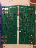
I told myself I should take a brake from building stuff, but now I'm well underway with a F5 Turbo. I'm building it dual mono, although I doubt I'll be able to tell the difference compared to a shared power supply. I've also added soft start and speaker protection.
Some photos below just in case someone can see something obviously wrong ...


Some photos below just in case someone can see something obviously wrong ...
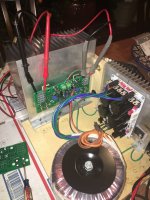
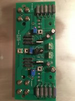
I haven’t been around much lately but I did a thing I wanted to share. 43 volt rails. Bias is set conservatively at .3volts over .4ohms. I have the mur diodes installed. I’ve really liked my f5 but wanted a bit more power. I look forward to trying the amps in my main system after a couple days playing on the shop speakers.
Thanks and enjoy.
E
Thanks and enjoy.
E
Attachments
-
 AA404D0A-AAD4-449E-ACE1-02EE3E216C99.jpeg820 KB · Views: 241
 -
 E83E5909-BD06-4C1C-8E5B-58B18386517D.jpeg481.6 KB · Views: 234
 -
 7E9080FE-DB59-4075-8EE0-10E0E793E2A0.jpeg499.9 KB · Views: 236
 -
 AFC97ED2-F836-4DEC-8FDE-351581EF8B2B.jpeg313.8 KB · Views: 228
 -
 FF59C459-3BE2-43D5-8052-831CAF7F406F.jpeg400.9 KB · Views: 227
I put everything together and and turned it on for the first time today. No smoke! It was quite straight forward to adjust bias. When adjusted I immediately hooked it up to my speakers and played some music. First impressions are very positive. Sounds great! And it's very quiet. And very hot ...


Can anyone give me the dimensions of the F5T boards? It's listed on the DIY audio website for the power supply boards but not the output boards.
I'd really like to lay all this out in AutoCad before making the jump
I'd really like to lay all this out in AutoCad before making the jump
Well I finally finished my F5 Turbo after a flame up. I replaced the four fried mosfets then rebiased the amplifier. Everything is mostly fine, aka it arrives at bias via normal means, no giant leaps in bias, no crazy voltage or heat.
However I have one issue that seems to be a major issue, the bias is constantly drifting upwards. It's very slow but noticeable and can't be left unattended due to this.
Has anyone seen this build drift badly? Is there a solution?
However I have one issue that seems to be a major issue, the bias is constantly drifting upwards. It's very slow but noticeable and can't be left unattended due to this.
Has anyone seen this build drift badly? Is there a solution?
Has anyone seen this build drift badly? Is there a solution?
1. Yes. If your heatsink is too large for the bias you set, this will happen. Because of the way large heatsinks work with multiple devices, you get a temperature gradient between devices and since you are only sensing a single device, the other can begin to run away.
2. Yes. Requires modification of the schematic beyond the scope of the discussion, and the PCB is not suitable for the required changes. See the original F5 article for the thermistor connection. Use a small value cap + series resistor to damp the thermistor action at HF in parallel with the Th+R combination. Touch the thermistor to the heatsink instead of the MOSFET.
This is not an approved modification, but almost guarantees impossibility of bias creep. The penalty is longer warm-up time because of thermal latency, and more fiddly bias adjustment.
Thank you so much. I will look into this modification. I can see the heatsink issue too, as it is a diyaudio store 5u case.
I can see how the thermistor mod isn't great for the pcb.
I can see how the thermistor mod isn't great for the pcb.
- Home
- Amplifiers
- Pass Labs
- F5 Turbo Builders Thread