Not really, no, but I'm hardly an expert. There seems to not be sufficient data in the datasheet (as is typical for ST) for me to infer whether the substitution would go well. For one the knee is not shown in the Vf/If graph, which makes me hesitate to reach a conclusion.
The MUR3020 is unique in even that line of diodes by having a fairly high forward voltage drop (at 25C case temp), whereas most diodes are built for low Vf. The lowering of Vf with increased temperatures is what is causing almost all of the known failures in the diode-based builds, and most high-current diodes are not even usable in the circuit because of their design that leans towards low Vf.
Running without the diodes has plenty of advantages, except the massive current headroom with the diodes. If you insisit on building with diodes, you can lower the source resistors to 0.3 ohms thus lowering the voltage across the diodes (and adding some brakes to the bias runaway that would occur) , but that changes the open-loop characteristics of the amplifier as well.

Also worth serious consideration… just build it without the diodes.
Sorry if this is a bit vague, dose the 100w V3 have any sonic improvement over the 50w V2.
my speakers are 86 db.
my speakers are 86 db.
Probably not.
Also remember that the difference between 50 and 100W is only 3db, and the expense of needing to make monoblocks, which doubles everything.
Monoblocks of course have some advantages with channel isolation, and the cool factor is significant.
Also remember that the difference between 50 and 100W is only 3db, and the expense of needing to make monoblocks, which doubles everything.
Monoblocks of course have some advantages with channel isolation, and the cool factor is significant.
and the cool factor is significant
Both figuratively and literally.
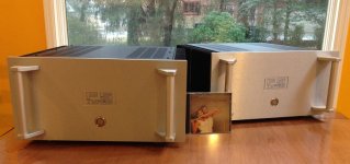
Attachments
hello, i have a problem with biasing F5Turbo stereo amp
i have 32,5V DC rails, U5 chassis.
i reached point that chassis temp is 56C , p-channel bias 268mV , n-channel bias 330mV and dc offset is oscillating from -10mV to 10mV.
my qestiostions are:
1. is it normal and i can proceed to reach 350mV on n-channel ?
2. if not where start to find possible reason ?
thanks for help
Hello Domdas,
first question: what kind of F5Turbo did you build? F5T V1 / V2 / V3?
If you have reached a temperature of 56° C on the heatsinks, you are getting into dangerzone for the Mosfets!

Was the temperature measured from outside the heatsink / inbetween the cooling fins / where the MosFets are mounted inside?
The difference of the voltage over the N-channel-Mosfets / bias-resistors and the P-channel devices is normally caused by matching those devices
(how good/ close?). But there can be other reasons!
With 330 mV over the bias resistors (what value in Ohm?) you are in a region where my F5T-V3-Monoblocks are running (but with higher railvoltage / around +- 42.7 V).
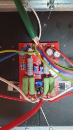
Perhaps you can post some pics from inside your amp, then we can see which version you have built.
A lot of experienced eyes / helpers here in this forum.
Cheers
Dirk 😉
first question: what kind of F5Turbo did you build? F5T V1 / V2 / V3?
If you have reached a temperature of 56° C on the heatsinks, you are getting into dangerzone for the Mosfets!
Was the temperature measured from outside the heatsink / inbetween the cooling fins / where the MosFets are mounted inside?
The difference of the voltage over the N-channel-Mosfets / bias-resistors and the P-channel devices is normally caused by matching those devices
(how good/ close?). But there can be other reasons!
With 330 mV over the bias resistors (what value in Ohm?) you are in a region where my F5T-V3-Monoblocks are running (but with higher railvoltage / around +- 42.7 V).
Perhaps you can post some pics from inside your amp, then we can see which version you have built.
A lot of experienced eyes / helpers here in this forum.
Cheers
Dirk 😉
What version are you building?
1. Given that you temps are already at 56C, you'll have to monitor and decide. The 20mV swing in DC offset at the output is acceptable. The F5 offset (if I am recalling correctly) was very stable. However, it does move a bit with temperature. In addition, do you have your inputs shorted?
2. I would not worry.
Pictures would help.
Edited - Hi Dirk! Posting around the same time. 🙂
Edited again - Until the bias on the N and P is roughly the same, I would definitely not worry about offset.
Matching N-channel and P-channel bias is not always possible, nor is it particularly important.
DC offset and tempature are the most important factors. You have good bias, good DC offset, and your temperature is high and should not be increased more, so you need to stop, place the lid on the top of the chassis, and see if bias+temperature remain stable.
DC offset and tempature are the most important factors. You have good bias, good DC offset, and your temperature is high and should not be increased more, so you need to stop, place the lid on the top of the chassis, and see if bias+temperature remain stable.
folow your suggestions i shorted input , place termistors closer to transistors and start biasing form 0
now i have 350mV on P-side and 280 mV on N-side. chassis temp 45C , DC offset form -2mV to 2mV
my only worry is 70 mV difference between P and N side.
now i have 350mV on P-side and 280 mV on N-side. chassis temp 45C , DC offset form -2mV to 2mV
my only worry is 70 mV difference between P and N side.
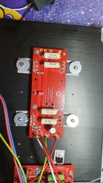
Attachments
If it really bothers you, remove the diodes and see if there’s a change.
There is almost always a difference between the P- and N- channel sides, due to the standard difference in the averages of Vgs between the two channel types. You seem to have a large difference, but as the DC offset is nicely controlled, I suggest not worrying about it and enjoying the amplifier.
🙂
There is almost always a difference between the P- and N- channel sides, due to the standard difference in the averages of Vgs between the two channel types. You seem to have a large difference, but as the DC offset is nicely controlled, I suggest not worrying about it and enjoying the amplifier.
🙂
Thank your for your advice. Now I am trying to bias second channel of amplifier. I checked all mosfet. They are in 3,390V- 3.410V Vgs range. I checked also diodes and V+/- = 33,6V. Problem start about 30mV of bias on N and P channels. Dc offset starts to constantly dropping. I correct it with increasing P1 but bias does not grow symmetrically. I stop reaching 300 mV on P side but bias does not want to pass 80 mV on N side. I checked P1 - 534ohm and P2 507 ohm. Where to find possible reason?
Best regards Dominik
Best regards Dominik
Bias is a function of P1 and P2, each pot biases one side of the amplifier. Increase P1 some, increase P2 some, etc… both sides need to be raised in a somewhat even fashion.
DC offset is also a function of both pots… as minimum offset is going to be found when the N and P sides are in relative balance, taking into account the various transistor measurments.
Question - you say N side never increases past 80mV? Is this using all the turns on the pot?
Can you set bias at 80mV on both sides and achieve 0DC offset? Please attempt.
of course i tried to increase both P1 and P2 but form some point I cant increase more P2 because dc offset dramatically drops into minus even more .
i cannot bias 80 mv on both sides. starting from 30 mV P side starts to rapidly grows and increase gap to N side
i cannot bias 80 mv on both sides. starting from 30 mV P side starts to rapidly grows and increase gap to N side
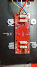
i removed diodes, but it really does not help much. after increasing P1 and P2 and increasing bias na P and N side symetrically and keeping offset around 0 i am reaching point ( it starting around 40 mV ) where offset starts to drop permanently, i tried to correct it by increasing P1 and then P2 but P side bias starts to grow up to 200 mV and N side bias drops to around 70 mV. i can not find balance because increasing P2 i push offset even more to minus
- Home
- Amplifiers
- Pass Labs
- F5 Turbo Builders Thread