Hi stereonutty,
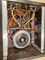
another approach that worked well - see pictures.
Perfboard, holes enlarged for the snap-in capacitors. Connection with 2.5 mm^2 solid wire (taken from standard European installation cable NYM 3x2,5 or 5x2,5; insulation stripped)
That would be approx. AWG 13 for our friends on the left side of the Atlantic 😉
Best regards, Claas

I like chokes too. I just put 4 Hammond 156B into a dual mono amplifier, replacing 0.1R in 44mF - 0.1R - 44mF filter, and the amp went from nearly quiet to totally quiet on my 103dB speakers.
I am also a fan of perf board and of course, the tightly twisted wires.
One tip on reducing the loop area further is to rotate the capacitors to reduce the gap between the grounds and the V+ and V- wires.
I am also a fan of perf board and of course, the tightly twisted wires.
One tip on reducing the loop area further is to rotate the capacitors to reduce the gap between the grounds and the V+ and V- wires.
Here's another point-to-point PSU of an appropriate scale for an F5T:

Jeff Young, That looks very nice! What chassis is that? Those look similar to Threshold heatsinks. I have been looking for something like that.
I'm a little hesitant to recommend it. While it has nice size (considerably bigger than most; those heatsinks are 70mm deep), the machining was a bit iffy resulting in a lot of stoning needed to mount the output transistors. (I use mica though; some of the more modern solutions such as Keratherm might avoid that issue?). That being said, I haven't found anything more suitable in that size class (and they're very reasonably priced).
https://www.ebay.ie/itm/27279965225...4EJIQ8wzP4MbXM45zisflgdg==|tkp:Bk9SR57WmLL4YA
https://www.ebay.ie/itm/27279965225...4EJIQ8wzP4MbXM45zisflgdg==|tkp:Bk9SR57WmLL4YA
Oh, and my amps are mono-blocks so I ordered 2, but they only sent me 1 set of handles for the back. I didn't use the handles anyway, so 🤷.
Thank you! I like the heatsinks. I intend to build a set of mono blocks and these may be the ticket. I use ceramic insulators with goop to take up the slack. Works well. I like being able to use them over again. Keratherm, from what I understand, isn't really reusable. You could almost have a piece of aluminum machined with bevels to make the center part of the front face that you wold see on the old S/X00 series amps.
I appreciate you sharing the link with me.
I appreciate you sharing the link with me.
Hi,
I have a F5T v2 that was built many years ago and never worked. Testing across the gain boards on TP1,2,3,4 are inconsistent and I cant get them to 0ohm. It doesn't let the smoke out under full power and the PS seems solid. Any suggestions?
I have a F5T v2 that was built many years ago and never worked. Testing across the gain boards on TP1,2,3,4 are inconsistent and I cant get them to 0ohm. It doesn't let the smoke out under full power and the PS seems solid. Any suggestions?
Take a bunch of well-lit, in-focus photos and post them here. We’ll get the hive mind started on the troubleshooting.
Take this with a gain of salt since I don't have any experience with the F5T boards. But my reading of it is that the TP1/TP2, TP3/TP4 resistance measurements need not be zero, but only that they are sufficiently low prior to the initial power up so that the output mosfets are off when power
is applied.
is applied.
Getting serious about this build. Got the heatsinks cut. Monoblocks with 6 pairs of output fets. Will have to cut the op boards to fit 6 but someone had the presence of mind to space the mounting hole around 2" 😀 so 6 will fit in 15.75" depth 4U pesante chassis.
I can mount fans to the back end and use these as heaters for my Mt mt cabin. It gets pretty cold in the high Rocky's so possibly looking to dissipate 20w-30w of heat per device. So 600va 30v secondary Hammond toroids should give about 40v rails. Any comments would be appreciated. Could not find any other builds ramping up the op fets. Papa definitely Bates is in the article, so why no babelfish F5 ? Is the single ended Aleph topo where I should be putting my energy?
me biased, like Alephs, no particularly like F5
though, it really depends of speakers of your choice, SPL, room size/ears distance to spks
though, it really depends of speakers of your choice, SPL, room size/ears distance to spks
The specs of the transformer should tell you what to expect under different loads. A good 600VA transformer should be OK.possibly looking to dissipate 20w-30w of heat per device. So 600va
See above. Also, it will depend on the PSU circuit you use. Don't think you've mentioned that. Either way, it should be OK if you're fine being within a few volts (under 40) particularly if you go for the higher Iq and/or a PSU design with higher voltage loss.30v secondary Hammond toroids should give about 40v rails.
Looks fun. The power from even 4 pair is more than enough for most people, but go for it! Are you planning the build with or without the 'turbo' diodes?Any comments would be appreciated. Could not find any other builds ramping up the op fets.
Totally different animal. Build both. 🙂 You could also consider a balanced F5T depending on what you're after.Is the single ended Aleph topo where I should be putting my energy?
Thanks for your comments! I have 2 Hammond 1182S30 30V @ 10.42a for each secondary with 117v ac mains. I generally get 120v here in Boulder CO. Not seeing any load test data, but could it be calculated based on the voltage regulation spec ?The specs of the transformer should tell you what to expect under different loads. A good 600VA transformer should be OK.
Using the diyAudio boards populated with kemet 10kuf 80v and 0R1 5w resistors pi filter ( 4 - 0R47, but I think one more would be good) . I've heard the term PSU impedance before and wonder if that is a quantifiable parameter? Is capacitor equivalent esr calculated the same as resistors ?See above. Also, it will depend on the PSU circuit you use. Don't think you've mentioned that. Either way, it should be OK if you're fine being within a few volts (under 40) particularly if you go for the higher Iq and/or a PSU design with higher voltage loss.
Consensus seems to favor no diodes, so that is the plan thus far.Looks fun. The power from even 4 pair is more than enough for most people, but go for it! Are you planning the build with or without the 'turbo' diodes?
Balanced seems like it would a better plan and I already have the boards.... Have you built a balanced F5 t v3? I'll have to look at F5X EUVL thread.Totally different animal. Build both. 🙂 You could also consider a balanced F5T depending on what you're after.
Thanks for your comment! my speakers are Dunlavy SM-1 87db SPL @2.83w 1meter. Nominal 5 ohm. Sealed box 1st order. They roll off at about 60hz at which point a Dunlavy SC-S2 sub takes over. My first thought was babelfish Aelph XJ with similiar number of output devices might not be the best fit.... but these bones could work to that end including the n channel output boards. 🙂me biased, like Alephs, no particularly like F5
though, it really depends of speakers of your choice, SPL, room size/ears distance to spks
- Home
- Amplifiers
- Pass Labs
- F5 Turbo Builders Thread