I took another look at my work and realised my mistake, too embarrassing to relate here. Amp now up and running wtih both sides at 55degrees C
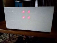
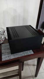
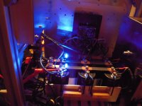
I must say this is a lovely amplifier and much nicer than my old F5 which I never really got on with ended up preferring the F6 or M2X but this amp has real synergy with my Dynaudios. Thanks for your direction. Phot of the amp posted below. I ran white pearl resin over the front panel with narrow hot glue filled holes in the aluminium for the LEDs. You can't see them when they are off.and they are diffuse when lit, the white centres on the photo are red in real life. Cheers
I must say this is a lovely amplifier and much nicer than my old F5 which I never really got on with ended up preferring the F6 or M2X but this amp has real synergy with my Dynaudios. Thanks for your direction. Phot of the amp posted below. I ran white pearl resin over the front panel with narrow hot glue filled holes in the aluminium for the LEDs. You can't see them when they are off.and they are diffuse when lit, the white centres on the photo are red in real life. Cheers
Attachments

I did a quick search of this thread but didn’t find an answer to my question, which is…am I able to build balanced F5T V3 monoblocks with the boards sold in the store?
yeah, if you think about classic bridging
sole difference being using XLR connector instead of 1+1 RCA, then channel HOT outputs
read F4 manual, covering principle
sole difference being using XLR connector instead of 1+1 RCA, then channel HOT outputs
read F4 manual, covering principle
Hi Kevin,
Yes, you can.
I've just built one, please check the post 6692 on the exact application.
There are 3 things different: XLR instead of RCA, link between 2 FE boards without connection of feedback resistors to ground and use only channel hot outputs.
Yes, you can.
I've just built one, please check the post 6692 on the exact application.
There are 3 things different: XLR instead of RCA, link between 2 FE boards without connection of feedback resistors to ground and use only channel hot outputs.
Diyaudiostore.comBonjour
j'aimerais me construire un f5 turbo mais ou pui je trouve le pcb et les composants sachant que j'ai déjà l'alimentation
merci
just so happens I have them too. Including matched Fairchilds

So I'm reading the F5 Turbo article in preparation to build an F5T V2. This led me back to the original F5 article where I stopped at Figure 3...it says "You can build both of these circuits and they will work". Attached are working examples of the preamplifier and amplifier circuits I built on a breadboard. You wouldn't believe me if I told you how long I spent building and troubleshooting these two. Maybe you would if I told you I grabbed an IRFP9240 out of the drawer instead of an IRFP150. 😡
Anyway, It was fun and a good learning experience! Not quite to the Turbo part though.


Anyway, It was fun and a good learning experience! Not quite to the Turbo part though.
Hi Everyone,
F5Tv2 build is moving up my projects, next build to be honest. I have not ordered all of the parts yet, still need to pick up the random bits and bobs from Mouser and the chassis. One question I have an open frame Ei Core transformer on my shelf that came from a friend. it is 24-0-24 at 700va. I am pretty sure that would work based on what is here. My question is the size. h x w x d = 160mm x 125mm x 125mm. Would that fit inside of the ModuShop 5U chassis? Just wondering as I will most likely find out once the chassis arrives but am trying to see if I should order from toroidy and get the standard toroid for this project.
Many thanks,
./e
See Here for internal dimensions and other valuable information.
https://diyaudiostore.com/collectio...mate-amplifier-chassis?variant=39313327128649
It will depend a bit if you use the internal perforated plate and how you set it up, but it should fit fine. As an example, I raise my perforated plates up a bit to allow a bit more room for my mains wiring between the bottom panel and the perforated plate. In my builds, I have approximately 180mm from the the top of the perforated plate to the top plate => working room.
Hope that helps.
Man, I had been bouncing between this build thread, the Store, and the Modushop site...feel like an idiot for missing the entire big section of 'Specifications'.See Here for internal dimensions and other valuable information.
https://diyaudiostore.com/collectio...mate-amplifier-chassis?variant=39313327128649
It will depend a bit if you use the internal perforated plate and how you set it up, but it should fit fine. As an example, I raise my perforated plates up a bit to allow a bit more room for my mains wiring between the bottom panel and the perforated plate. In my builds, I have approximately 180mm from the the top of the perforated plate to the top plate => working room.
Hope that helps.
Helped beautifully!
I'm rather a novice when it comes to electronics, especially PSU's. I decided to use 8 capacitors of 10,000 uF per rail for my F5 Turbo build, but thus can't use the diyAudio Store PCB's. Now I'm thinking of making something myself, using the diyAudio PCB as a templete, and E-Cu strips 1mm thick and 5 and 20mm wide, connected to eachother with thick copper wire. Is this a good idea or a very stupid one? E.g. would the impedence be to low?
Have a look at this pdf from firstwatt https://www.firstwatt.com/pdf/art_f5_turbo.pdf
the power supply looks like your description and simple, but large, to build
the power supply looks like your description and simple, but large, to build
Why not get a 2nd transformer and make it completely dual mono…? You can use the PSU pcb, and get all the other advantages of dual mono.I'm rather a novice when it comes to electronics, especially PSU's. I decided to use 8 capacitors of 10,000 uF per rail for my F5 Turbo build, but thus can't use the diyAudio Store PCB's.
Hello stereonutty,
sure you can make a symmetrical PSU with big fat copper bars and big caps on your own.
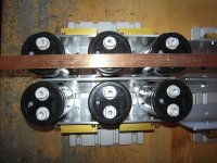
I also did it for my IXYS-hockeypuck-monoblocks. And it works nice!
But you should know what you do... 🤔 Such a PSU doesn't accept mistakes.
For example a M5-screw falling inbetween a + and a - terminal of big caps shortening them...
bigbadaboom!

Building the PSU with the PSU-boards from the diyAudio store is easier. My opinion.
And at first start up - please use a dimbulbtester. Especially if you are not that experienced.
Safety first! You can't see, you can't hear those electrons flowing. And better not to smell the result
of being in a hurry...
Cheers
Dirk 😉
sure you can make a symmetrical PSU with big fat copper bars and big caps on your own.
I also did it for my IXYS-hockeypuck-monoblocks. And it works nice!
But you should know what you do... 🤔 Such a PSU doesn't accept mistakes.
For example a M5-screw falling inbetween a + and a - terminal of big caps shortening them...
bigbadaboom!
Building the PSU with the PSU-boards from the diyAudio store is easier. My opinion.
And at first start up - please use a dimbulbtester. Especially if you are not that experienced.
Safety first! You can't see, you can't hear those electrons flowing. And better not to smell the result
of being in a hurry...
Cheers
Dirk 😉
Attachments
Mainly because of expence and I already bought a 800VA transformer. My concerns with the idea as discribed are if there will be any stability issues or not.Why not get a 2nd transformer and make it completely dual mono…? You can use the PSU pcb, and get all the other advantages of dual mono.
Safety first, absolutely! And check, check, check and check again. Point is that my description of my idea was not complete. First I have caps of the snap in type, and my idea is sort of a upside down version of the type of PSU you made (that looks beautiful by the way). See my sketch. The copper strips I plan to cover with teflon tubing with cut outs for the solder points. The epoxy plate is the type of perforated bare (no copper layer) used for loudspeaker crossovers. Now I wonder if capacitive effects between the copper strips and the steel bottom plate of the casing will cause problems?Hello stereonutty,
sure you can make a symmetrical PSU with big fat copper bars and big caps on your own.
I also did it for my IXYS-hockeypuck-monoblocks. And it works nice!
But you should know what you do... 🤔 Such a PSU doesn't accept mistakes.
For example a M5-screw falling inbetween a + and a - terminal of big caps shortening them...
bigbadaboom!
Building the PSU with the PSU-boards from the diyAudio store is easier. My opinion.
And at first start up - please use a dimbulbtester. Especially if you are not that experienced.
Safety first! You can't see, you can't hear those electrons flowing. And better not to smell the result
of being in a hurry...
Cheers
Dirk 😉
https://www.zenmod.in.rs/babelfish-xj-or-jx-or-whatever/Safety first, absolutely! And check, check, check and check again. Point is that my description of my idea was not complete. First I have caps of the snap in type, and my idea is sort of a upside down version of the type of PSU you made (that looks beautiful by the way). See my sketch. The copper strips I plan to cover with teflon tubing with cut outs for the solder points. The epoxy plate is the type of perforated bare (no copper layer) used for loudspeaker crossovers. Now I wonder if capacitive effects between the copper strips and the steel bottom plate of the casing will cause problems?
View attachment 1095879
🙂
Scroll.
- Home
- Amplifiers
- Pass Labs
- F5 Turbo Builders Thread