I replaced the tip 31 and tip 32 ......I also replaced the mosfets on the N and P channel boards......there was some 16gauge wire that I used to connect from the fe board to the N and P boards. They were too big and they really didn't fit properly. I used 20 gauge Teflon wire........the only thing I can think of is that I left the input cables disconnected when I attempted to set bias.Did you do anything else other than remove the diodes? You do have to go back to 0 and start the biasing procedure from scratch.
The difference between 346 and 336 is 3% and well within resistor tolerance, so it's nothing to worry about.
Inputs need to be shorted for bias setting. At zero position of trimpots upto 500mV is fine on output, as the 'zero' is not always zero but a few dozen ohms at half-turn. I don't see anything to worry about, you should attempt the setting procedure as per documentation and report back.
All the parts were purchased from the diyaudio store......prior to that I used eBay stuff cause diystore was out of stock on f5 turbo kit .........before I tried to change all of this the bias was pretty even.I replaced the tip 31 and tip 32 ......I also replaced the mosfets on the N and P channel boards......there was some 16gauge wire that I used to connect from the fe board to the N and P boards. They were too big and they really didn't fit properly. I used 20 gauge Teflon wire........the only thing I can think of is that I left the input cables disconnected when I attempted to set bias.
I broke one of the legs on the mosfet trying to take it out. Can I just solder a wire . Or do I have to change all my mosfets again?Inputs need to be shorted for bias setting. At zero position of trimpots upto 500mV is fine on output, as the 'zero' is not always zero but a few dozen ohms at half-turn. I don't see anything to worry about, you should attempt the setting procedure as per documentation and report back.
Oh my. You should pull all the MOSFETs and test them, you may have put a few heat cycles through them so better to see if they still match correctly.. Usually a wire works just fine as long as it's properly soldered.
Changing them all out is safer, but more expensive. Really your call.
Changing them all out is safer, but more expensive. Really your call.
I found the problem with th left channel. I had the output wire and the gate wires crossed on the fe board to the driver boards. ...after fixing that the reading seem pretty normal. I am wondering if I did any damage ?Oh my. You should pull all the MOSFETs and test them, you may have put a few heat cycles through them so better to see if they still match correctly.. Usually a wire works just fine as long as it's properly soldered.
Changing them all out is safer, but more expensive. Really your call.
Most times a transistor either works, or it doesn’t. If you had no smoke, and no insane bias levels causing overheating but no blowup, and bias and offset levels are stable I’d say your good to go 🙂I found the problem with th left channel. I had the output wire and the gate wires crossed on the fe board to the driver boards. ...after fixing that the reading seem pretty normal. I am wondering if I did any damage ?
You can hang the extra MOSFETs on your wall, in antistat, and write «fets from the hands of the sea ranch dweller», making a poster out of them 🙂
regards,
Andy

Yeah, if you remember I did the same thing with the input wires on the korg nutube that you pointed out . quess I am suffering from a little dislexia. I am glad this thing is more of a learning tool than a amplifier. When I decide I want good sounding equipment I will just buy a real pass lab amp ..but I am still tryin to get better and still enjoying this.Most times a transistor either works, or it doesn’t. If you had no smoke, and no insane bias levels causing overheating but no blowup, and bias and offset levels are stable I’d say your good to go 🙂
You can hang the extra MOSFETs on your wall, in antistat, and write «fets from the hands of the sea ranch dweller», making a poster out of them 🙂
regards,
Andy
Good day everyone. after removing all the diodes and replacing all my mosfets i ended up with about 450mv per channel and looks like 52c degress on the heatsinks. I have a question about p3 on the fe board. How would i take all the 2nd harmonics out. I want to see what it sounds like with out the soul. i do not have a scope,.also if anybody could tell me what a good beginner ocilloscope would be to purchase. Not tryin to break the bank.
Picoscope 2204 w or w/o probes
https://www.tequipment.net/Pico/220...=cpc&msclkid=e79bcf92ebba15294797adda023cc94e
https://www.tequipment.net/Pico/220...=cpc&msclkid=e79bcf92ebba15294797adda023cc94e
wow! thanks thats so cheap. you need a computer ? for this
thank youwow! thanks thats so cheap. you need a computer ? for this
Hello to the DIYers!
I am somewhere closer to the final stage to complete the F5v3 balanced monoblocks.
I've pre-biased ams with a lab PS, then assembled the amp in a chassis and started it with a variac: after reaching 25% of the nominal voltage my bridge rectifier blew off: traces on the PCB exploded.
My PS is: 800VA 2*27V trafo, 8*47000 uF 40V Sikorel caps, pair of 159ZL 10A 2.5mH inductors.


I decided to disassemble the entire amp and check the PS separately:
1. All the 8 caps are functioning properly, RLC meter shows correct capacitance, after applying 30VDC from the Lab PS all the caps charge well and discharge with bleeder.
2. Next I disconnected rectifiers and applied Lab PS to the positive and negative rails separately, without attaching the ground bus between rails: two separate rails were functioning OK.
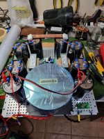
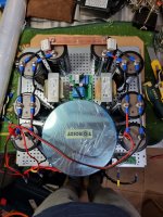
3. After I installed the ground Bus between the rails and V+ rail charged properly while V- rail behaved like a short: 0V and max current of the lab PS (left channel on the picture).
4. Next I checked the other power supply (for the second monoblock) in the very same fashion and got the same result: positive rail is OK, negative behaves like a short.

I spent the entire night on it I can't find anything wrong in the wiring or individual components, thus asking for some community opinion on what could go wrong.
I have a lab PS, Variac and high quality multimeter with RLC to check any of the assumptions.
Thanks in advance!
I am somewhere closer to the final stage to complete the F5v3 balanced monoblocks.
I've pre-biased ams with a lab PS, then assembled the amp in a chassis and started it with a variac: after reaching 25% of the nominal voltage my bridge rectifier blew off: traces on the PCB exploded.
My PS is: 800VA 2*27V trafo, 8*47000 uF 40V Sikorel caps, pair of 159ZL 10A 2.5mH inductors.
I decided to disassemble the entire amp and check the PS separately:
1. All the 8 caps are functioning properly, RLC meter shows correct capacitance, after applying 30VDC from the Lab PS all the caps charge well and discharge with bleeder.
2. Next I disconnected rectifiers and applied Lab PS to the positive and negative rails separately, without attaching the ground bus between rails: two separate rails were functioning OK.
3. After I installed the ground Bus between the rails and V+ rail charged properly while V- rail behaved like a short: 0V and max current of the lab PS (left channel on the picture).
4. Next I checked the other power supply (for the second monoblock) in the very same fashion and got the same result: positive rail is OK, negative behaves like a short.
I spent the entire night on it I can't find anything wrong in the wiring or individual components, thus asking for some community opinion on what could go wrong.
I have a lab PS, Variac and high quality multimeter with RLC to check any of the assumptions.
Thanks in advance!
Attachments
A lab PSHello to the DIYers!
I am somewhere closer to the final stage to complete the F5v3 balanced monoblocks.
I've pre-biased ams with a lab PS, then assembled the amp in a chassis and started it with a variac: after reaching 25% of the nominal voltage my bridge rectifier blew off: traces on the PCB exploded.
My PS is: 800VA 2*27V trafo, 8*47000 uF 40V Sikorel caps, pair of 159ZL 10A 2.5mH inductors.
View attachment 1041171
View attachment 1041168
I decided to disassemble the entire amp and check the PS separately:
1. All the 8 caps are functioning properly, RLC meter shows correct capacitance, after applying 30VDC from the Lab PS all the caps charge well and discharge with bleeder.
2. Next I disconnected rectifiers and applied Lab PS to the positive and negative rails separately, without attaching the ground bus between rails: two separate rails were functioning OK.
3. After I installed the ground Bus between the rails and V+ rail charged properly while V- rail behaved like a short: 0V and max current of the lab PS (left channel on the picture).
4. Next I checked the other power supply (for the second monoblock) in the very same fashion and got the same result: positive rail is OK, negative behaves like a short.
View attachment 1041170
I spent the entire night on it I can't find anything wrong in the wiring or individual components, thus asking for some community opinion on what could go wrong.
I have a lab PS, Variac and high quality multimeter with RLC to check any of the assumptions.
Thanks in advance!
also, beware: do not, ever, prebias using a lab PSU. Never. Too much a risk of errors (current limiters can kick in, you risk turning the pots way too high).Hello to the DIYers!
I am somewhere closer to the final stage to complete the F5v3 balanced monoblocks.
I've pre-biased ams with a lab PS, then assembled the amp in a chassis and started it with a variac: after reaching 25% of the nominal voltage my bridge rectifier blew off: traces on the PCB exploded.
My PS is: 800VA 2*27V trafo, 8*47000 uF 40V Sikorel caps, pair of 159ZL 10A 2.5mH inductors.
View attachment 1041171
View attachment 1041168
I decided to disassemble the entire amp and check the PS separately:
1. All the 8 caps are functioning properly, RLC meter shows correct capacitance, after applying 30VDC from the Lab PS all the caps charge well and discharge with bleeder.
2. Next I disconnected rectifiers and applied Lab PS to the positive and negative rails separately, without attaching the ground bus between rails: two separate rails were functioning OK.
3. After I installed the ground Bus between the rails and V+ rail charged properly while V- rail behaved like a short: 0V and max current of the lab PS (left channel on the picture).
4. Next I checked the other power supply (for the second monoblock) in the very same fashion and got the same result: positive rail is OK, negative behaves like a short.
View attachment 1041170
I spent the entire night on it I can't find anything wrong in the wiring or individual components, thus asking for some community opinion on what could go wrong.
I have a lab PS, Variac and high quality multimeter with RLC to check any of the assumptions.
Thanks in advance!
I suggest you start from scratch. You seem to have started with the end productf biasing up. This comes last.
connect IEC to tranny, power up with variac. All good? Connect to rectifiers x 2 (I see only one, maybe dual? Looks very small for that purpose).
power up and test rectifiers with variac.
connect to caps. Redo power up procedure.
all good?
then connect one channel of the amp, at ZERO bias (nulled pots, whatever).
power up using variac.
all good?
try to bias one chan to 80% of target.
all good?
connect other chan, repeat.
regards,
Andy
Hi Andy!
I can't get the power supply working, not the amplifier.
I deliberately disconnected the rectifiers before connecting the new ones to check that the rest of the circuit is OK, looks like it is not.
Tranny is OK, rectifiers (new ones) are OK, separate rails connected are OK, once I connect the ground Bus between caps I get a "short" behaviour on the V-.
- Home
- Amplifiers
- Pass Labs
- F5 Turbo Builders Thread