Hi, I have an 2 kw toroidal transformer with 2x41V vac. Is this an option for F5 Turbo V3 , 100 W ? Thanks
Hello, can anybody here explain what the reverse procedure would be to remove the diodes on my f5 turbo? Do I just unsolder them? Do I remove any resistors to?......I want the more stable build.
Snip the legs off and remove the mounting screws. No other changes are needed. You should set bias to zero and start the biasing procedure from scratch.
Thank youSnip the legs off and remove the mounting screws. No other changes are needed. You should set bias to zero and start the biasing procedure from scratch.
So now that I don't have the diodes in place and having the 5 u chassis with the dual heat sinks on each side. How high can I go on the bias?Snip the legs off and remove the mounting screws. No other changes are needed. You should set bias to zero and start the biasing procedure from scratch.
The usual target is 25-30C above room temperature after an hour or so, maybe longer. Up to 1.6A should be easy, maybe more depending on how cool the ambient is.
You want to keep device dissipation below about 30W, which limits the maximum bias with 32V rails to 1.8A or so. This would be about 450mV across the 2x 1R resistors. You will basically be heat-limited in either case.
You want to keep device dissipation below about 30W, which limits the maximum bias with 32V rails to 1.8A or so. This would be about 450mV across the 2x 1R resistors. You will basically be heat-limited in either case.

I'm very curious to hear your opinions regarding, bias procedure, sound quality, with and without the diodes.Hello, can anybody here explain what the reverse procedure would be to remove the diodes on my f5 turbo? Do I just unsolder them? Do I remove any resistors to?......I want the more stable build.
sad day: I fried it again. I still have extra MOSFETs and can fix it again -
- but am I doing something wrong cranking it up like I did?
- Is there some electrical thing I should be doing to perhaps blow a fuse before frying internal circuitry: way more of a hassle than a fuse, for instance. I had 3.15a slow blow in there before.
- can I test MOSFETs in place, or do they have to be de-soldered to test?
You can start with pulling out the MUR3020 diodes, and don't use them. I bet they are the reason for the blowups.
MrDrewk, given you've had a number of failures I too would suggest getting rid of the diodes if you are still using them.
Also, what are your rail voltages? I saw a mention of using the Harris IRFP9141. They're nice, but only rated at 60V. So depending
on your rail voltages and how hard you are driving the amp, it's quite possible for the voltage swing of an F5 turbo to exceed that rating.
Edit: My apologies. The Harris IRFP9141 is rated at 80V. The 60V seems to be for the Samsung IRFP9141.
Last edited:
I've removed the MUR3020W diodes: D1,D2,D3,D4, each both sides, 8 total. In my case they are SDUR60P60WT. They look(ed) important.
@Dennis Hui 26volt rails
I ended up replacing all IRFP9240 (x2) P-channel, and IRFP240 (x2) N-channel MOSFETs on both sides, 8 total. Of the 8, 3 measured incorrectly, and I think were fried. I did not put an 8amp fuse in and set them on fire this time around.
I discovered it was impossible to measure the MOSFETs in place; they had to be removed from the board to give reasonable measurements using digital multimeter in diode mode using these instructions.
Just wanted to make double sure I understood you guys right!
Side note: I'd tried to hunt down a hum earlier. I tried increasing the mains wires from 16awg to 12awg, and removed the green fluorescent AC switch from that line. Maybe that will make a difference.
I will slowly bring back up to 120v with dim-bulb and variac, and re-bias. Fingers crossed!
Attachments

I had some washers under there before, but these little MOSFETs seem plenty strong for just this screw.
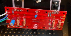
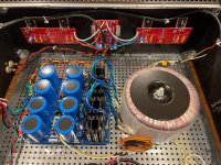
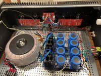
Here are some big pics of the build as it is at the moment.
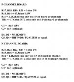
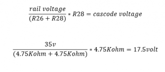
Above I said I was pushing 26 volt rails, nope! It's 35 volts. Not even a close guess. Now this has me going back to re-examine my cascode formula to make sure R26, and R28 are correct. Double checked, R26 and R28 are both 4.7kOhm.
So that works out to 17.5volts cascode voltage. I'll attach the big pics.
Here are some big pics of the build as it is at the moment.
Above I said I was pushing 26 volt rails, nope! It's 35 volts. Not even a close guess. Now this has me going back to re-examine my cascode formula to make sure R26, and R28 are correct. Double checked, R26 and R28 are both 4.7kOhm.
So that works out to 17.5volts cascode voltage. I'll attach the big pics.
Attachments

I also recommend the use of washers on the mosfets and adding standoffs to the PCBs.
The cascode voltage using 4.7K resistors is fine with 35V rails. You're still limiting the Vds of the jfets to about 17V and unless your jfets have very high Idss, their dissipations will be ok.
The cascode voltage using 4.7K resistors is fine with 35V rails. You're still limiting the Vds of the jfets to about 17V and unless your jfets have very high Idss, their dissipations will be ok.
@Mdrewk
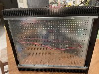
Do you have anyway to measure HS temps after an hour of running. They look on the small side to me. Also is it setting under that tight shelf in earlier pic? It needs some open air to breathe and cool properly. NP advice on temps by holding hands on HS are very close to accurate. If 60C or above you will not be able to hold your hands on for 10sec.
Do you have anyway to measure HS temps after an hour of running. They look on the small side to me. Also is it setting under that tight shelf in earlier pic? It needs some open air to breathe and cool properly. NP advice on temps by holding hands on HS are very close to accurate. If 60C or above you will not be able to hold your hands on for 10sec.
Hi Everyone,
2 years since starting research I finally have a functioning V3 Monoblock (still need to build the other). Just have some questions about bias and setting the amp up to have good long term stability.
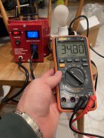
Last week during biasing, these were the conditions:
Does anyone have advice what a good long term bias would be for my case? I'd love to know some of the math behind Sangram's figures from Tuesday (to figure out maximum bias for 56.6 V rails). I know many have recommended removing the diodes, but I would like to keep them to maintain the "turbo" spirit. Happy to run a conservative bias to stay safe. Thanks for any advice!
2 years since starting research I finally have a functioning V3 Monoblock (still need to build the other). Just have some questions about bias and setting the amp up to have good long term stability.
Last week during biasing, these were the conditions:
- wall voltage = 124.5 V, temp = 24.7 C (most extreme conditions the amp will encounter)
- 339.2 mV / 334 mV across the output test points
- .001 V dc offset
- Rail voltage = 56.6 V fully loaded
- Forgot to record temperature, but I think the hottest point on the heatsink was ~55 C
Does anyone have advice what a good long term bias would be for my case? I'd love to know some of the math behind Sangram's figures from Tuesday (to figure out maximum bias for 56.6 V rails). I know many have recommended removing the diodes, but I would like to keep them to maintain the "turbo" spirit. Happy to run a conservative bias to stay safe. Thanks for any advice!
Congratulations!
See page 11 of the article. I think you've found your long-term bias point, and/or you may back off a touch more if you think your temps may ever get a bit warmer. I like the way you estimated the most extreme cases, but you also know the risks. If the wee bit of extra bias is worth it, then you can run closer to the ragged edge. You've run it with no load / no signal. If you run it into a low impedance to hot temps per the article, you may refine it just a weeeeeee bit.
In this case, I don't know how temps compare in Class A operation (temps should reduce as SPL climbs) to once you've driven the thing to what I can only assume to be crazy SPLs and it transitions. Then, I'd assume temps rise again. You've probably read about a few flame-ups, and you're already certainly above the "fraidy-cat" point. Is it worth it to push further? Only you can answer your own risk vs. reward. Mine's also speculation vs. practice.
re: Sangram's calcs - I'll let them respond, but if I read back far enough... that's with respect / advice to someone that was removing their diodes. Not applicable to you. However, I'd still wait for another thought, preferably from Sangram. Again, speculation on my part w/o context.
Others may differ in their approach. My
Enjoy!!!!!
Edited to add for clarity - I certainly don't mean to imply that you should test the amp with speakers attached vs. a dummy load. A better way to say it would be ... tested into a low impedance load at a power level that would likely result in crazy SPL if speakers were attached. Do you really even need to test your amp under such conditions if it's not likely to ever operate under them during foreseeable use? Longwinded, but more clear.
So first of all, congratulations from staring down the conducting diode and recovering from it. That certainly puts you in the ranks of fearless amplifier builders. 🙂
Sangram suggested keeping the dissipation per device under 30W. Let's try working out what that implies.
You have +/-56.6V rails. So for simplicity let's say +/-57V. The current through each transistor = voltage across source resistor / (0.5ohm (two 1-ohms in parallel) ) = 2 x voltage across source resistors.
The power dissipation per device = ( voltage across each device x current) ~ 57 x (2x voltage across source resistor) ) ~ 114 x voltage across source resistor.
If we want this <30W this means the voltage across each source resistor should be < 30/114 ~0.263V.
The diodes place a limit on this voltage. In your case 0.345V was already causing problem. You can try eyeballing based on the published curves, but when I tried, all I could get was what we already know (0.3-ish volt when the diodes can start to conduct) and that doesn't take into account parts variations.
Papa suggested 0.3V (and conservative fusing) for us Fraidy cats so ~0.27V will satisfy this condition and keep the dissipation in the 30W range.
Edit: I second my friend ItsAllInMyHead's point that only you can decide where on the risk/reward curve you want to land. I hope the above example at least helps with seeing how a dissipation limit on the mosfets can affect things.
Last edited:
- Home
- Amplifiers
- Pass Labs
- F5 Turbo Builders Thread