Hi all,
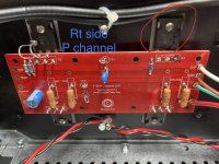
Quick question about pcb stuffing for V3 monoblocks. Following the circuit diagram C2, C4, R12 and TH2 (and P-channel corresponding parts) should only be installed to one of the output boards on each side, correct? Only reason that I ask is that I have seen monoblocks with C2/C4 installed on all output boards. I just assume the change in capacitance is insignificant.
See picture - from my understanding the second (right) output board on each side is complete (minus diodes/fets of course)
Cheers & enjoy the weekend!
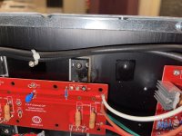
I managed to smoke and catch fire to one of the MOSFET IRFP 9240 shortly after New Years.
Too late, I noticed one of the speaker wires had come out of the binding post and touched the chassis. Not sure if that led to this failure.
I had cranked the amp up past where it should have been. It cut out, I immediately powered it off and swapped to a different amp (New Years eve in full swing!) yesterday I put in another fuse, it blew. I put in a larger fuse, and was greeted with smoke and fire out of one of the MOSFET.
Certainly that will have to be replaced. Anything else I should do here? Sim bulb tester, variac, go slow post results?
thanks a million happy new year!
Attachments
Whooops!
You let the smoke out. it’s super difficult getting it back in, so replacing the obvious stuff is in order, as you mention.. 🙂
You let the smoke out. it’s super difficult getting it back in, so replacing the obvious stuff is in order, as you mention.. 🙂
Source resistor definitely gone unless you used the diode, in which case it'll be OK. Gate resistor and JFET on opposite side from the MOSFET need to be checked, ideally you need an entirely new half output stage. Good luck!
@Sangram thank you for the guidance! Been re-reading a bunch of my notes to see if I can find answers that I've overlooked.
1. the "source resistors" I think are R17-R23 on P and N channel boards?
2. could I just replace all the components (all except the MOSFETs) on the P channel board with fried Q4: MOSFET IRFP 9240, then double check continuity on the silicone traces.
3. Rather than buying the whole matched kit (F5T V1/2 transistor kit $80 sold out), I can get the F-5 Transistor kit for $30, in stock, that does have the IRFP 9240s - but not the JFETs that you mentioned.
That might get me where I need to be?
From what I can see you have the diodes in, so the source resistors are OK. You should replace the entire output stage, and use a brake resistor on the power supply rails (10 ohm, 1/2 watt), back the bias down to zero before powering up, and start moving the trimmers for a bias of about 100ma (50mV across the resistors). If all goes OK it means you can remove the brakes and bias it up properly.
If you have smoke from the brake resistors or unusual offset, it means the JFETs will need to be replaced.
I would also remove the diodes permanently. As has been mentioned, stability with the diodes is not guaranteed in all conditions, and temperature can have a funny impact on when the diodes conduct.
Sounds good. I'm pretty n00b here, so forgive my basic questions. I'd love to get all the parts ordered so they're ready to go. If something might need to be replaced, I'd like to plan on just replacing it to eliminate that possibility.
Is "entire output stage" going to be Q3 and Q4 on P-Channel Board, AND Q5 and Q6 on N-Channel Board? And all other resistors, capacitors, thermistor, and
Replace entire output stage - Is this BOTH P and N Channel boards? Or only the components on the P-channel board with the burnt MOSFET? Including:
Might need to replace JFETs those are in stock, so I'll just order them. Those are in Q1 and Q2 on Front End Board.
remove diodes Which diodes are you referring to? From the schematic, it looks like D1-4 are the MUR3020 and the only diodes on the board - though the Mouser page calls them rectifiers.
brake resistors I don't know what these are either. 10ohm 1/2 watt resistor between the PSU + and the +Ve on the FE Board?
Is "entire output stage" going to be Q3 and Q4 on P-Channel Board, AND Q5 and Q6 on N-Channel Board? And all other resistors, capacitors, thermistor, and
Replace entire output stage - Is this BOTH P and N Channel boards? Or only the components on the P-channel board with the burnt MOSFET? Including:
- R17-20, R13-14, R11
- TH1
- C1, C3
- D1,D2 MUR3020W (not in stock at diyaudiostore, would the rectifiers from mouser work #MUR3020WTG $3.41?)
- Q3, and Q4 (Q4 being the fried one)
Might need to replace JFETs those are in stock, so I'll just order them. Those are in Q1 and Q2 on Front End Board.
remove diodes Which diodes are you referring to? From the schematic, it looks like D1-4 are the MUR3020 and the only diodes on the board - though the Mouser page calls them rectifiers.
brake resistors I don't know what these are either. 10ohm 1/2 watt resistor between the PSU + and the +Ve on the FE Board?
Difficult seeing as I don't have the boards on hand and I've never actually used those boards.
But - Gate resistors, and the MOSFETs on the output board that burnt. You do have to check the other polarity as well. The best way I know to do this is to use a light bulb tester when powering up after your rebuild.
Diodes are the 4x MUR3020 on the output boards, you do have to remove them from all 4 output boards if you choose the more stable build process. Must be the D1 to D4, there aren't any others in the circuit.
The brake resistors are an alternative to a variac or a light bulb tester, they basically fuse open if there's a problem, usually almost immediately. Not as safe as the variac, not as sure as the lightbulb, but they do do their job. You need one on each polarity, and see if either/both smoke when powered up. Stating the obvious, but the bias pots need to be set all the way down to zero ohm for any of these checks.
Thank you @Sangram! To circle back to your previous comment "remove diodes permanently" really?!?! Those MUR3020 appear to be important pieces of the Output Boards! All four output boards in there can function without the MUR3020 attached at all? Or: do you mean remove them as part of the bias up procedure? 6L6 didn't mention a thing about that in the power up description.
How about the matching MOSFETs. The F5T uses 4xIRFP240, and 4xIRFP9240, and is sold out. Should I plan on replacing all of them on the P and N channel boards. I can only get the F4 Transistor kit that comes with 6 of each, so I certainly can replace all of them.
How about the matching MOSFETs. The F5T uses 4xIRFP240, and 4xIRFP9240, and is sold out. Should I plan on replacing all of them on the P and N channel boards. I can only get the F4 Transistor kit that comes with 6 of each, so I certainly can replace all of them.
The diodes are actually optional. The output current of the F5/T is limited by the resistors between rail and source. The bias point is usually below the conduction point of the diodes, so when the current increases a bit the diodes conduct and bypass the resistors.
Trouble is, at elevated temperatures the diodes will conduct a bit earlier, and then a bit earlier again. Depending on how you bias it, it is possible to reach an operating condition when the diode will remain in conducting state when it is not supposed to, and then you will have insta-failure.
For more power, I usually resort to adding more outputs in parallel. I routinely use three pairs, but for more it's better to look at something like the BA3, which is essentially a F5 driving a F4.
I really would not recommend using anything other than matching MOSFETs. You can have a few left over, if everything works you can try a vanilla F5 with your spare pairs. I find that the best sounding of this type of amp anyway (my opinion only).
Sounds good! I feel like I can make this order and move forward. Thank you very much. Doing a regular F5 might be a good next project. Thanks Sangram
There is a bias point beyond which the diodes are a liability- above .5 or .6 Volts they bypass the resistors meant to moderate bias drift. You can disable them as part of your tests.
Side note, the next batch of F5T semis go to the store next week.
Side note, the next batch of F5T semis go to the store next week.
it's been a long time since I built my class A amp, with my peasant AudioNirvana classic 8 then even peasant SIT L'amp with only driven by dcb1 has more than enough gain. sorry to M2 and J2 are laying around without usage 🙂
but now I'm building another challenging speaker project with dynaudio esotar2 650 and 110 driver which are 4 ohm. 1st try will be using M2 but more juice will be required
I have been using Talema for all my amp because there is a good guy who imported them and sell it locally. there are many custom wound toroid but not my taste for class a.
so my option is limited, either 2x25V 225VA (peasant VA because my FW clone use 2x18V 225VA) or 2x30V 500VA
if I go with 2nd option,how many output pairs for V3 built is recommended for 4ohm load? anyway this will be monoblock chassis
don't worry about heatsink, I can build a new chassis as big as needed 🙂
I am building the f5 turbo 2 with 32 volts at the rail is there a recommended fuse for this setup
Hi.Can we use MUR3020PT instead of MUR3020W ? I could not find a difference but maybe i miss something so i am asking
Got the stuff I'm going to start replacing things in the next day. I have a Variac, dim-bulb tester, and three digital multimeters for a slow power up, and the re-bias procedure.
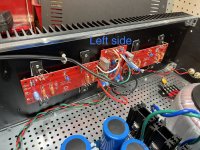
I will replace "Right side P Channel" Q3, Q4 = IRFP9240 with Harris IRFP9141
I got parts from the F4 Transistor Kit. From that page "The current batch of kits includes Harris IRFP9141 instead of the International Rectifier version. These have better distortion characteristics and are a sonic upgrade, but it should be noted they are rated for 100V."
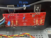
I will replace "Right side N Channel" Q5, Q6 = IRFP240, with IRFP240 from same F4 Transistor Kit above
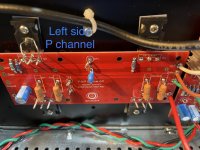
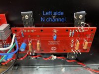
Should I replace Q3, Q4, Q5, and Q6 on the Left Side of the amp as well?
I'm planning on checking other components vs the other side of the amp to see if there are any differences that would trigger replacing that too.
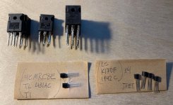
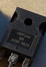
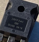
From the MOSFETs I got in the kit, four of the the IRFP240 are identical, and two are slightly different. All six say "IRFP240" and have the I<symbol>R, but the third line differs. Four say "606B 9616" and two say "6V5R 9623". Perhaps that's not important?
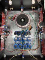
I'm planning on swapping the PSU and transformer front to back so it looks more like all the others around here! I had some hum previously that would be great if it was gone.
I will replace "Right side P Channel" Q3, Q4 = IRFP9240 with Harris IRFP9141
I got parts from the F4 Transistor Kit. From that page "The current batch of kits includes Harris IRFP9141 instead of the International Rectifier version. These have better distortion characteristics and are a sonic upgrade, but it should be noted they are rated for 100V."
I will replace "Right side N Channel" Q5, Q6 = IRFP240, with IRFP240 from same F4 Transistor Kit above
Should I replace Q3, Q4, Q5, and Q6 on the Left Side of the amp as well?
I'm planning on checking other components vs the other side of the amp to see if there are any differences that would trigger replacing that too.
From the MOSFETs I got in the kit, four of the the IRFP240 are identical, and two are slightly different. All six say "IRFP240" and have the I<symbol>R, but the third line differs. Four say "606B 9616" and two say "6V5R 9623". Perhaps that's not important?
I'm planning on swapping the PSU and transformer front to back so it looks more like all the others around here! I had some hum previously that would be great if it was gone.
Attachments
-
 IMG_6683.JPG731.2 KB · Views: 299
 -
 IMG_6684.JPG610.1 KB · Views: 282
 -
 IMG_6685.JPG584.9 KB · Views: 241
 -
 IMG_6686.JPG466.1 KB · Views: 233
 -
 IMG_6687.JPG469.3 KB · Views: 226
 -
 IMG_6688.JPG419.9 KB · Views: 213
 -
 IMG_6689.JPG447.6 KB · Views: 279
 -
 IMG_6690.JPG527.3 KB · Views: 219
 -
 IMG_6691.JPG376.1 KB · Views: 203
 -
 IMG_6692.JPG36.6 KB · Views: 264
 -
 IMG_6693.JPG26.5 KB · Views: 287
Hello Mrdrewk,
what you read on the MosFets (606B 9616) is a production code / date. So your IRFP240 are from two different batches.
Don't worry - the diyAudio-shop matches them really well.
I wish a successful rebuild of your F5T! No hard party music with this amp anymore... 😉
Cheers
Dirk
what you read on the MosFets (606B 9616) is a production code / date. So your IRFP240 are from two different batches.
Don't worry - the diyAudio-shop matches them really well.
I wish a successful rebuild of your F5T! No hard party music with this amp anymore... 😉
Cheers
Dirk

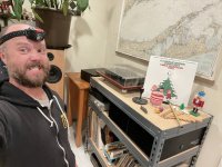
I'm super happy to report that I replaced the MOSFETs as I described above, and it all worked swimmingly. I revisited the biasing procedure that 6L6 posted via chuckd and it powered up nicely. The Harris MOSFETs were a little more finicky than the other side with the original ones I'd used:
original: 0.352V, 0.352V, 0.002V offset
Harris: 0.357V, 0.333V, 0.000V offset
But the procedure said anything less than 50mV with 0 offset, good to go, so: good to go!
Super happy. Here's last nights session in all it's glory.
Thanks again friends: @verticalmammal @cubicincher @Sangram and @Nelson Pass
Attachments

- Home
- Amplifiers
- Pass Labs
- F5 Turbo Builders Thread