when I was replying few days ago, I did check at regular digi, Mou, TME, Conrad, Buerklin
evidently, I was not thorough enough, didn't found them so just mentioned ggl
and even now - I can find 100R/1W at Conrad, not 3W
Metal Film (some vendors are having Films and Oxide in same category)
evidently, I was not thorough enough, didn't found them so just mentioned ggl
and even now - I can find 100R/1W at Conrad, not 3W
Metal Film (some vendors are having Films and Oxide in same category)
to carsten.witt #6562
Hello Carsten,
good price for the Panasonic - resistors....🙄
Cheers
Dirk 😀
Hello Carsten,
good price for the Panasonic - resistors....🙄
Cheers
Dirk 😀
It may have been covered in the 650+ but pages in this thread but has there been any opinion on the sound from the original spec'd mosfets to the currently available ones?
I have used all 3 mosfet types (Fairchild, IRF and now Toshiba 2SK1530/2SJ201) in the same amp. There is a difference but it's not night and day. I guess my preference would be Toshiba, Fairchild then IRF in that order but the basic character of the amp does not change dramatically, really we are talking about the last 5% of performance gains. Increased bias or good PSU caps has a more dramatic effect.
Try it
Thank you, I'll take what you wrote into consideration and try it right away.
I have used all 3 mosfet types (Fairchild, IRF and now Toshiba 2SK1530/2SJ201) in the same amp. There is a difference but it's not night and day. I guess my preference would be Toshiba, Fairchild then IRF in that order but the basic character of the amp does not change dramatically, really we are talking about the last 5% of performance gains. Increased bias or good PSU caps has a more dramatic effect.
Thank you, I'll take what you wrote into consideration and try it right away.
I moved forward with a few anti-hum techniques in the Hifisonix article @Ben Mah steered me towards.
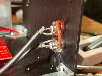
1. drilled another RCA hole next to an existing one, and mounted the RCA inputs next to one another.
2. connected (bonded) RCA sheaths together inside the case.
3. routed new, longer Belden coax wire around the front of the case avoiding the transformer
4. experimented with rotating the transformer +/- 45deg
The hum is definitely much quieter, still there, but a level I can live with.
Ah, and does anyone have any additional guidance on adding a "Hum Breaking Resistor" into this amp somewhere? I don't think there is one in the PCBs I got from Diyaudiostore. Specifically, where would I add it, and what the heck should it be?
Page 37/73 in the Ground-Loops.pdf
Someone also mentioned the ground loop lifter, diode bridges?, that I'm pretty sure is the KBPC3504 from Mouser. I'd like to get one of those going too, if you think it will help.
this looks like 6l6 guide included them here.
the article
http://hifisonix.com/wordpress/wp-content/uploads/2019/02/Ground-Loops.pdf
Attachments
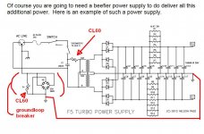
The Thermistor and bridge rectifier are probably superior, I have been using a 5.1 ohms 3-5 w resistor and two large diodes, one forward and one reverse polarity, all in parallel, from the power supply as a star signal ground to the chassis ground. Works as well. A bit less expensive but not too much. Your choice. 🙂
to johnhenryharris #6571
Hello johnhenryharris,
I use both. Also your described version. I use the 35A-bridge-rectifier+thermistor-version for poweramps and the resistor+reverse-diode-version for preamps and similar devices with lower powerdraw.
There are many ways to make a groundloop-breaker...
Greets
Dirk 😉
Hello johnhenryharris,
I use both. Also your described version. I use the 35A-bridge-rectifier+thermistor-version for poweramps and the resistor+reverse-diode-version for preamps and similar devices with lower powerdraw.
There are many ways to make a groundloop-breaker...
Greets
Dirk 😉
Attachments

I moved forward with a few anti-hum techniques in the Hifisonix article @Ben Mah steered me towards.
1. drilled another RCA hole next to an existing one, and mounted the RCA inputs next to one another.
2. connected (bonded) RCA sheaths together inside the case.
3. routed new, longer Belden coax wire around the front of the case avoiding the transformer
4. experimented with rotating the transformer +/- 45deg
The hum is definitely much quieter, still there, but a level I can live with.
Ah, and does anyone have any additional guidance on adding a "Hum Breaking Resistor" into this amp somewhere? I don't think there is one in the PCBs I got from Diyaudiostore. Specifically, where would I add it, and what the heck should it be?
Page 37/73 in the Ground-Loops.pdf
Someone also mentioned the ground loop lifter, diode bridges?, that I'm pretty sure is the KBPC3504 from Mouser. I'd like to get one of those going too, if you think it will help.
this looks like 6l6 guide included them here.
the article
http://hifisonix.com/wordpress/wp-content/uploads/2019/02/Ground-Loops.pdf
Whether or not the direct chassis/audio gnd connection is contributing, can be tested easily. Simply disconnect the connection, turn the amp on, and listen. Be careful though 🙂 But maybe you allready tried that?
Maybe I missed it, but have you tried rotating the transformer/moving it out of the chassis? Edit: missed it

Edit:
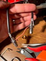
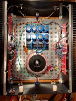
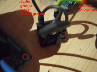
1: are those your transformer shield cables unconnected? Those orange ones.
2: Your AC connections and the transformer are close to both inputs/outputs and the gain stages. How you tried reversing the PSU layout?
Regards,
Andy
Last edited:
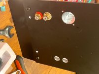
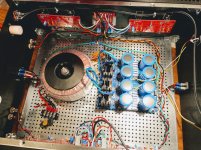
Also, you have the audio gnd wires for left and right channel on opposite sides of your PSU/at each side of the junction were high currents flow between pos and neg half of gnd plane, in effect creating a loop area were nasty gremlin currents might mess you up at night. Twist the tips of the yellow and the green for left and right, stick in the same euroblock hole, and see what happens. Also, the high current gnd connection is right on the junction, which is actually a good place. You could try moving that too, to the opposite side of the junction/opposite side of the PSU as the audio gnd connections, and see if it makes a difference.
This, and disconnecting audio from safety gnd for a QUICK test, might provide some further insight.
Please also post your R values for the CRC, and check whether hum level decreases and increases with bias level.
Regards,
Andy
This, and disconnecting audio from safety gnd for a QUICK test, might provide some further insight.
Please also post your R values for the CRC, and check whether hum level decreases and increases with bias level.
Regards,
Andy
Last edited:
yup, I tried it: no change.Whether or not the direct chassis/audio gnd connection is contributing, can be tested easily. Simply disconnect the connection, turn the amp on, and listen. Be careful though 🙂 But maybe you already tried that?
Maybe I missed it, but have you tried rotating the transformer/moving it out of the chassis? Edit: missed it
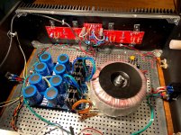
Yes: they're unconnected. I accidentally got the wrong transformer that had some additional outputs that I didn't need. It was an AN-8225 800VA 25V, looks identical to their current AN-8425 800VA 25V with a 18V and 12V pairs, 4 extra wires total. I snipped them shorter, bent each over, and put heat-shrink over them to keep them insulated.1: are those your transformer shield cables unconnected? Those orange ones.
I have not yet done that. Do you mean, putting the transformer at the front of the case and the PSU in the back? I wanted a front mounted switch, so I ran two more mains AC wires up front there to a pretty green switch.2: Your AC connections and the transformer are close to both inputs/outputs and the gain stages. How you tried reversing the PSU layout?
Will do! I see you caught I didn't use the same color for each Front end board, I ran out of the right gauge/color.Twist the tips of the yellow and the green for left and right, stick in the same euroblock hole, and see what happens.
Will do that too! "high current gnd" is the fat green wire coming off the top of the PSU (front by AC switch). So I'll twist each Front End board ground together, jam in same euroblock ground, and try moving the big PSU ground wire to the opposite side and back to see if that makes any difference.Also, the high current gnd connection is right on the junction, which is actually a good place. You could try moving that too, to the opposite side of the junction/opposite side of the PSU as the audio gnd connections, and see if it makes a difference.
I tried that one, and it didn't make a difference.This, and disconnecting audio from safety gnd for a QUICK test, might provide some further insight.
I'll revisit this again in a few weeks: gotta head to work here for a bit and make some cheddar. Thanks so much for your responses!Please also post your R values for the CRC, and check whether hum level decreases and increases with bias level.
You allready did a very good job chasing the hum imo!
I am a hum chaser too, not 100% successful either, if any comfort 🙂
One thing: Do only one of the suggestions at a time. For example, the audio gnd twisting together as one process, moving the fat gnd wire as a separate process, and both processes at the same time as a third test, etc.
Regarding the reversal of the PSU, I meant what you thought. Though, honestly, I don’t think that is the main issue. And since you allready got it down to acceptable levels, perhaps a few more small adjustments are all that is needed?
And if time allows, reversal might be a good idea. Keeping the most noisy and magnetic parts away from small signal circuitry and wiring is apparently very smart. Transformers, diode bridges, AC wiring and the ripple-carrying DC wires from the bridges especially.
I haven’t built the T yet, so I don’t know how ripple sensitive it is. However, the specced 0R067 in the CRC suggests it is quite tolerant wrt PSRR. But it is also a very high bandwith amp, so it probably picks up this and that from the circuits surroundings.
Good luck, and please, share what your profession is and is like! Cheddar making, sounds kinda cool 🙂 I like cheddar.
Last edited:
You already did a very good job chasing the hum imo!
I am a hum chaser too, not 100% successful either, if any comfort 🙂
...
Good luck, and please, share what your profession is and is like! Cheddar making, sounds kinda cool 🙂 I like cheddar.
I'm susceptible to flattery. I do almost nothing flattering around these forums, that's for sure! But this amp kicks ***, and the nicest one I've ever owned for sure. I drive boats for a living. Here's me at work 🙂
Thank you for that excellent advice, that I'll follow slowly.
Attachments

I might have to build one then, sounds like I should 
Your job, man, I think I would have liked that 🙂
Your job, man, I think I would have liked that 🙂
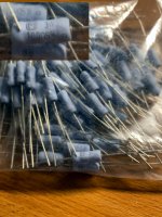
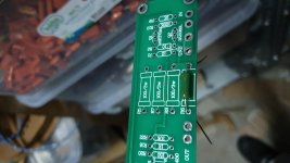
Feedback resistors
Hi. I have large stock of 100R vishay g202 4w resistors in stock. I do not have mox ones and i could not find them in our country right now. I also have 0r47 as emitter resistors .Can i use them ? Is there any disadvantage to use these vitreous wirewound resistors in feedback and as emitter resistors?
Hi. I have large stock of 100R vishay g202 4w resistors in stock. I do not have mox ones and i could not find them in our country right now. I also have 0r47 as emitter resistors .Can i use them ? Is there any disadvantage to use these vitreous wirewound resistors in feedback and as emitter resistors?
Attachments
Last edited:

- Home
- Amplifiers
- Pass Labs
- F5 Turbo Builders Thread