
You sure you wired your rectifiers correctly, and if using the lab PSU, that you wired it correctly to the caps?Hi Andy!
I can't get the power supply working, not the amplifier.
I deliberately disconnected the rectifiers before connecting the new ones to check that the rest of the circuit is OK, looks like it is not.
Tranny is OK, rectifiers (new ones) are OK, separate rails connected are OK, once I connect the ground Bus between caps I get a "short" behaviour on the V-.
been looking at your cap wiring. First thought I found an error, but now I see it looks fine. Hmmm
Last edited:
Yes, initially I powered up the supply without the ground bus attached, it was OK on the full voltage.You sure you wired your rectifiers correctly, and if using the lab PSU, that you wired it correctly to the caps?
been looking at your cap wiring. First thought I found an error, but now I see it looks fine. Hmmm
Hmmm. By OK do you mean all readings? Neg full rail voltage on the neg tap referenced to positive, and positive full rail voltage on the positive tap referenced to neg? Please confirm this, and also post possible voltage differences between the positive and negative rail.Yes, initially I powered up the supply without the ground bus attached, it was OK on the full voltage.
if voltages are good and of the correct polarity, I cannot fathom/understand how it could short. In other words: if all is good @ the rails, the bus should not short.
disconnecting the gnd bus and measuring your rails, is step one. Then we can move on and help you further along.
By OK I mean: I measured + 36V on the last cap of the positive rail (between + and - of the cap, no bus attached) and measured -36V on the last cap on the negative rail between - and + of the cap.Hmmm. By OK do you mean all readings? Neg full rail voltage on the neg tap referenced to positive, and positive full rail voltage on the positive tap referenced to neg? Please confirm this, and also post possible voltage differences between the positive and negative rail.
if voltages are good and of the correct polarity, I cannot fathom/understand how it could short. In other words: if all is good @ the rails, the bus should not short.
disconnecting the gnd bus and measuring your rails, is step one. Then we can move on and help you further along.
Then I attached the bus and amps and damaged the rectifier after power up.
Initially my rectifiers were small for the task, this is for sure, I've already bought monolithic bridges.
I assume following steps to debug:
1. Check if the V- on the Lab PS is connected to ground or not, if not - continue struggling and checking individual components, if yes - step 2;
2. Assemble variac + trafo + bridges, check the supply (already checked, was OK);
3, Assemble varial + trafo+ bridges + filter caps without the ground bus, check voltages;
4. Add the bus back, repeat step 3.
My guess is that the lab PS is fooling me with the short on negative side, though better to double-check.
I think you are right. Since nothing seems amiss, the lab PSU might be the culprit. I have never had much luck using a lab PSU for huge PSUs or high current outout boards. Preamps are different tho.By OK I mean: I measured + 36V on the last cap of the positive rail (between + and - of the cap, no bus attached) and measured -36V on the last cap on the negative rail between - and + of the cap.
Then I attached the bus and amps and damaged the rectifier after power up.
Initially my rectifiers were small for the task, this is for sure, I've already bought monolithic bridges.
I assume following steps to debug:
1. Check if the V- on the Lab PS is connected to ground or not, if not - continue struggling and checking individual components, if yes - step 2;
2. Assemble variac + trafo + bridges, check the supply (already checked, was OK);
3, Assemble varial + trafo+ bridges + filter caps without the ground bus, check voltages;
4. Add the bus back, repeat step 3.
My guess is that the lab PS is fooling me with the short on negative side, though better to double-check.
I’d use monolithics as you plan to, then wire the whole PSU back to IEC inlet, and connect the variac there. Don’t use the lab psu. Consider whether you want to safe it by then connecting one and one stage of the PSU bit by bit, to ensure every bit works. Ending with the gnd plane.
in your case, the lab PSU can be ok to test the front end and output boards functionality, biased very very low. But nothing more, I say but with limited experience and also little knowledge if your specific lab PSU.
Also please check that you actually have configured properly the lab supply as a bipolar (+/-) power supply. One supply I've used required you to run the rails in a special mode (not independent) so that one rail is the positive and the other is the negative voltage which just tracks the positive rail. Perhaps your user manual will have some mention if anything special needs to be done for a bipolar supply.
even if drawn somewhat backwards, at least to my brain - it'll work as that
you must find a problem where you connected it different to schematic
You may mean the same things, but for clarity. the second part should be 'if no - Step 2')I assume following steps to debug:
1. Check if the V- on the Lab PS is connected to ground or not, if not - continue struggling and checking individual components, if yes - step 2;
Simplified.
Is V- for your lab supply connected to mains earth?
YES - STOP and set up the lab supply properly.
NO - Continue
Is it set up properly (check manual) for a bipolar supply?
YES - Continue
NO - Stop and set it up properly as a bipolar supply.
Also.... if your PSU has current limiting. I'd strongly advise taking advantage of that feature.
Double, triple, quadruple check. 😉My guess is that the lab PS is fooling me with the short on negative side, though better to double-check.
Sorry for double posting others' suggestions, but getting Step 1 done properly will save you headaches.
Edited for clarity re: separating mains earth to V- and setting up for bipolar supply. I had it wrong. DOH! 😀
I think you have 2 separate issues. First if your lab supply shares a common ground between the 2 then your basically shorting one of the supplies to ground. Check your manual. You can check for continuity between the grounds of each supply. Disconnect supply and power it off before. It needs to be open circuit. If not then you can't use that supply for what you're trying to do, or possibly there's a way to separate them. Check your manual.
Then double check the way your rectifiers are wired. Your schematic and cap bank wiring looks ok. It may also be an issue with the transformer phasing. Your schematic is only showing the phasing dot on one of the secondaries. If you find nothing wrong with the rectifier wiring/boards then swap the secondary wires on one of the rectifiers and try again. (see bulb info below)
The other step by step advice about starting with zero bias you should follow. Don't try to "pre bias" the amps. Only bias in situ after a successful fire up.
Instead of a variac wire a 40-60 watt light bulb in series with the hot side of the AC line for initial fire up. If the light stays lit brightly for more than a second or 2, as the caps charge, then you have a problem. If there is an issue the bulb will Use the extra current and light up brightly instead of sending it through your amp and save your parts and a bunch of heart ache. Remove the bulb after everything checks out and before biasing.
Gents, thank you for your help!
Indeed, the bridge on the negative rail was shorted to the ground. It took me some time to find a short, eventually I found out that the stud on Sikorel caps is not isolated from the alu can.
As there is very little chance to buy anything with delivery to Russia right now, I found that 1/4 plumbing rubber seal fits nicely and isolates the can from the steel base, finally the PS functions as intended.
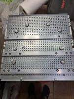
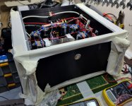
I also found a way to lift the perforated baseplate and increase its stiffness a lot: there is a standard rectangular alu profile that does the job well and prevents the base from bending under heavy transformers.
Indeed, the bridge on the negative rail was shorted to the ground. It took me some time to find a short, eventually I found out that the stud on Sikorel caps is not isolated from the alu can.
As there is very little chance to buy anything with delivery to Russia right now, I found that 1/4 plumbing rubber seal fits nicely and isolates the can from the steel base, finally the PS functions as intended.
I also found a way to lift the perforated baseplate and increase its stiffness a lot: there is a standard rectangular alu profile that does the job well and prevents the base from bending under heavy transformers.
Attachments
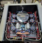
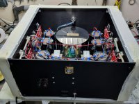
Happy to share that yesterday night I launched both channels, It took me almost a year to build both.
I am not sure that this is the first balanced F5 Turbo here, though definitely not a very popular build option.
Some specs:
35v DC supply;
800VA trafo per monoblock;
188.000 uF capacitance per rail and 376.000 uF per monoblock, all 105C Epcos Sikorel;
CLC power supply, tx2575 gate stopper resistors;
Thermal protection, push button with Hypex soft start;
SSR speakers protection with instant shut off;
I managed to reach 350mV per board at 35V supply having 55 degrees celsius at the heatsink after 4 hours.
These little beasts do sound wonderdufilly, thank you guys for your help and special thanks to Nelson for the design!
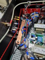
There is a little 60Hz hum in both channels, I suspect that the "link" (red wire crossing the box in the middle) which is connecting feedback loops is picking AC interference, when I disconnected it the hum was totally gone. I will consider revising the link cabling along with the input wires to stay away from magnetic fields.
Thanks!
I am not sure that this is the first balanced F5 Turbo here, though definitely not a very popular build option.
Some specs:
35v DC supply;
800VA trafo per monoblock;
188.000 uF capacitance per rail and 376.000 uF per monoblock, all 105C Epcos Sikorel;
CLC power supply, tx2575 gate stopper resistors;
Thermal protection, push button with Hypex soft start;
SSR speakers protection with instant shut off;
I managed to reach 350mV per board at 35V supply having 55 degrees celsius at the heatsink after 4 hours.
These little beasts do sound wonderdufilly, thank you guys for your help and special thanks to Nelson for the design!
There is a little 60Hz hum in both channels, I suspect that the "link" (red wire crossing the box in the middle) which is connecting feedback loops is picking AC interference, when I disconnected it the hum was totally gone. I will consider revising the link cabling along with the input wires to stay away from magnetic fields.
Thanks!
Attachments

Last edited:
Is there a good reasen for using +/-35VDC in a balanced amp? That makes this amp a class A/B amp. Putting out around 260W class A/B at 8ohm. But only about 8W class A at 8ohm. But i find it strange that you can't get higher standing current. Are you sure there is 350mV pr output board, and not 350mV pr output transistor? If the latter, you get around 30W class A at 8ohm.
Last edited:
Hi Audiosan!
I'd say that considerations are mostly practical: I started the project 7 years ago after purchasing chassis, transformers and capacitors.
Initially I wanted to build v3 single ended monoblock but after I changed my speakers to the TL1 Troels project and they do require some power.
Thanks!
I'd say that considerations are mostly practical: I started the project 7 years ago after purchasing chassis, transformers and capacitors.
Initially I wanted to build v3 single ended monoblock but after I changed my speakers to the TL1 Troels project and they do require some power.
Thanks!
350mV per board sounds very low. That's 175mA per measurement - the actual bias is twice each measurement divided by the resistor value. Balanced mode with diodes sounds very hairy, hope it works out for you.
I bet it's 350mV between testpoints. That makes it 350mV (700mA) pr output fet. And 1,4A pr half of each side of each the monoblock.
That makes a total dissipation of 35VDC X 1,4A X4 halfs = 196W total dissipation pr monoblock.
That makes a total dissipation of 35VDC X 1,4A X4 halfs = 196W total dissipation pr monoblock.
You are right, I posted the same comment above.I bet it's 350mV between testpoints. That makes it 350mV (700mA) pr output fet. And 1,4A pr half of each side of each the monoblock.
That makes a total dissipation of 35VDC X 1,4A X4 halfs = 196W total dissipation pr monoblock.
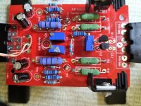
HI, some guidance would be appreciated. I've largely completed a F% turbo V2 as a dual mono. ONe side works perfectly but I'm having trouble with the front end board on the other side. I did install Q7 and Q8 in the opposite postions but hat has been corrected. The mian issue I have is that I can't get the resistance to zero from the two pots (It did set itself correclty the first time), it sits on 30K ohm whatever I do. I have checked and eplaced the Jfets and checked the pots which appear to be good. I've attached a photo of the relvant board.
Attachments
- Home
- Amplifiers
- Pass Labs
- F5 Turbo Builders Thread