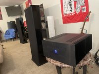
Thank you both for the detailed replies - it is much appreciated. And as my understanding develops, I realize how lucky I am to have survived runaway conducting diodes 🤣 A few other things that could be relevant: I have the 5Ux500mm chassis, so 25% more heatsink than the typical 5Ux400mm. Based on the phrasing in the article, it seems that the 30 watt limit is due to heat, so I could maybe go slightly higher than 30. I'll be using these amps to power Mirage M3si towers (Impedance: 6 ohms nominal, 4 ohms minimum. Sensitivity: 83dB at 2.83V - notoriously hard to drive).
At the present bias, I calculated 38 watt dissipation per device. This is the edge of stability in my case with no load. If my understanding is correct, there is risk at this level while driving low impedance loads since the diode current could generate additional heat? I assume this, or something similar, is the reason for loading the amp as described on page 11 in the article. As ItsAllInMyHead was getting at, it seems estimating how far below this point is "safe" is difficult without actually driving a low impedance load.
In the next day or two I plan on moving the amp to where it will be used (cooler and wall voltage closer to 120) and monitoring stability. I might move the bias down towards 300 for some extra headroom depending on the temp. I just ordered all the parts for DC protection today, so speaker test is on the horizon!
Thanks again everyone for chiming in.
I wouldn't worry about the heat from the diodes.
If your concern is wanting to have more bias without the diodes going into conduction
you can reduce the resistance of the Source resistors. Of course you still have to keep
an eye on bias drift.
If your concern is wanting to have more bias without the diodes going into conduction
you can reduce the resistance of the Source resistors. Of course you still have to keep
an eye on bias drift.
Thanks Papa for the reply. I might ask - is there a reason why temperature would be higher driving a low impedance load as opposed idling with no load?
It's been a while since I looked, but with +/-57V rails and 4 pairs of output, you'll have about 2-2.1A of total bias, or 500-525mA per pair.
This translates to 250mV across the source resistors. You should not exceed that unless you're prepared for consequences. At 345mV you were at 40W per device - not dangerous, but not advisable either. One of the big issues is getting heat fast enough tto the heatsink. With pulsed loads this is rarely an issue, but with continuous dissipation the ~0.9C/W j-c resistance means that the die is running 40 degrees above the case temperature, which is in turn 10 degrees above heatsink temperature. When the heatsinks are at 55C, it means the MOSFET die is 105C for a 40W dissipation. At 30W, you get under the 100C mark, which is a bit safer.
This translates to 250mV across the source resistors. You should not exceed that unless you're prepared for consequences. At 345mV you were at 40W per device - not dangerous, but not advisable either. One of the big issues is getting heat fast enough tto the heatsink. With pulsed loads this is rarely an issue, but with continuous dissipation the ~0.9C/W j-c resistance means that the die is running 40 degrees above the case temperature, which is in turn 10 degrees above heatsink temperature. When the heatsinks are at 55C, it means the MOSFET die is 105C for a 40W dissipation. At 30W, you get under the 100C mark, which is a bit safer.
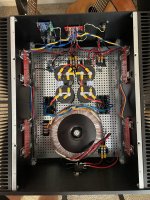
It plays music! Thanks to Nelson Pass for offering the design and everyone that’s helped answer questions along the way. Now to build the second one…
Attachments
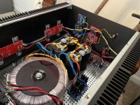


Hello, f5 turbo question,can anybody tell me if its ok for the thermister to touch the leg of the mosfet on the back side. when you fold the mosfet over comes really close to the back where you solder the mosfet
Hello crooner2264,
I would never bend the thermistor to touch the MosFets - solderleg. Why? - It was reported from one or two members, that the insulation colour /paint on the thermistors 'head' went off because of heat. The thermistors head got blank. If it is touching another blank metalpart (leg of the Mosfet) there is a high danger of a short with its consequences. The thermistor should touch the plasticbody of the Mosfet.
We like to run our amps in hot classA - but no shorts or fire please...


Cheers
Dirk
I would never bend the thermistor to touch the MosFets - solderleg. Why? - It was reported from one or two members, that the insulation colour /paint on the thermistors 'head' went off because of heat. The thermistors head got blank. If it is touching another blank metalpart (leg of the Mosfet) there is a high danger of a short with its consequences. The thermistor should touch the plasticbody of the Mosfet.
We like to run our amps in hot classA - but no shorts or fire please...
Cheers
Dirk
True, however you do want the thermistor to touch the body of the mosfet. You don't want it to touch the washer or any of the legs, only the plastic body. Put a small dab of thermal paste on the body and bend the thermistor over to it to touch just the body.
thanks for response. the amplifier was already up and running but it did not sound right to me. tip 31 and tip32 were both under 150hfe .the new ones from the diyaudio store are in the 250 range ...Initially when i first build this thing i could not get past 200mv of bias..i ended up having to change 2 resistors to get the bias to go up but i think i had to do that because of the low hfe on tip transistor? not sure,but i think maybe should be able to go back to the original resistors that were in the schematic?....I also purchased the complete mosfet /diode kit from the diy store although i will not be using the diodes i feel confident that it will sound better with reputable parts versus ebay stuff.
Those transistors are part of the cascode curcuit. and the only purpose of that curcuit is to lower the rail voltage for the J-fets. They got nothing to do with the bias, or any sound what so ever. The bias problem is that R5/R6 often need to be a lot more then 1Kohm when the J-fets got lowish idss.
ok got it tip 31,32 protect the j fets so I have 32v rails and all my resistors are 10k
Those transistors are part of the cascode curcuit. and the only purpose of that curcuit is to lower the rail voltage for the J-fets. They got nothing to do with the bias, or any sound what so ever. The bias problem is that R5/R6 often need to be a lot more then 1Kohm when the J-fets got lowish id
And will it be possible to reach 500milivolts on the bias with no diodes? I have the 5 u chassis from the diyaudio store.
Of course it will be possible. But unless you have an extremely big chassis, it will get frighteningly hot. The die of the fets will be extreme. Total dissipation will be 128 watts per channel. I will not be surprised if your sinks reach 65 degrees.And will it be possible to reach 500milivolts on the bias with no diodes? I have the 5 u chassis from the diyaudio store.
even in the 5U400, 128 watts is a lot. Target 100 watts, meaning a drop of 390mV across the source resistors @ 0A78 Iq per device. And I recommend Keratherm. See what you get and work from there 🙂
if you are extremely confident in your building skills, use a torque wrench @ 0N9 to tighten the fets, and Keratherm, and provide very good ventilation, 128 watts is possible in the 5U400. But it is not nescessarily a good idea, especially in the long run.
like Mighty sez: how can one enjoy the music if there is a risk of the amp blowing up? And also, are you sure you need those amounts of current?
regards,
Andy
It will not. The mosfet internal thermal resistance (j-c) is close to 1C/W and the best possible coupling methods will be 0.5C/w. This means the die will be running ~50 degrees above case temperature. If you have a couple fans blowing on the sink and can keep the sinks at or below 45C, then you can probably get away with it.
The second thing to consider is the resistor dissipation. At 1A, two 1 ohm resistors will each be dissipating 0.5W continuously (and more when the current increases). The typical thermal resistance will be 200C/W (generously) so unless you have Caddocks that can mount to the sinks, you will see 50C above ambient on the resistors (typically, 90 to 100C). This will slowly cook the resistors over time.
When you need a lot of current, it's better to just use more pairs.
It will not. The mosfet internal thermal resistance (j-c) is close to 1C/W and the best possible coupling methods will be 0.5C/w. This means the die will be running ~50 degrees above case temperature. If you have a couple fans blowing on the sink and can keep the sinks at or below 45C, then you can probably get away with it.
The second thing to consider is the resistor dissipation. At 1A, two 1 ohm resistors will each be dissipating 0.5W continuously (and more when the current increases). The typical thermal resistance will be 200C/W (generously) so unless you have Caddocks that can mount to the sinks, you will see 50C above ambient on the resistors (typically, 90 to 100C). This will slowly cook the resistors over time.
When you need a lot of current, it's be
thanks for your response,it seems ive run into a bit of a problem. After changing the mosfets and eliminating the diodes ...the left channel defaults to 250mv dc offset and seems to not be acting anything like it did when i first completed this build. .....I got scared so i disconnected v+ and the v- and moved on to the right channel. ......p channel 346mv...n channel 336MV...........dc offset at -15mv ...........if i try to get any closer on the bias the dc becomes very high....please any suggestions? did i possibly short out the Mosfets in the left channel? .......why is the right channel so imbalanced?
Did you do anything else other than remove the diodes? You do have to go back to 0 and start the biasing procedure from scratch.
The difference between 346 and 336 is 3% and well within resistor tolerance, so it's nothing to worry about.
The difference between 346 and 336 is 3% and well within resistor tolerance, so it's nothing to worry about.
Last edited:
After changing your mosfets, you need to reset P1 and P2 to minimum value prior to start up since you don't know what current level the new mosfets will be running at.
Then you just go through the bias procedure again.
The goal is to keep DC offset low. Note that your 'bias' values of the N and P side are just the voltage across one pair of source resistors on each side. You can measure across each pair of source resistors to make sure each mosfet is running ok. The variations can come from the mosfets and the source resistors. As long as the differences in the measured voltages aren't big, you'll be fine.
- Home
- Amplifiers
- Pass Labs
- F5 Turbo Builders Thread